Defining Raceway
Parts
-
Open the drawing Raceway.dgn.
-
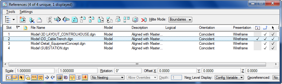
Deactivate Display option for all reference files except
DD_CableTrench.dgn.
-
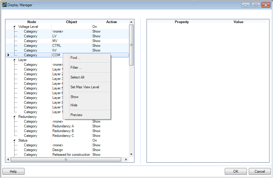
Start the
Display
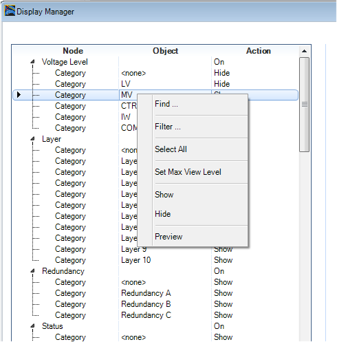
Manager.
-
Select Voltage Level Category entries without MV, press right
mouse button and Hide.
-
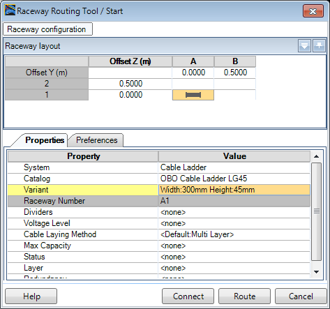
Use the function
Raceway
Router and press the Connect button.
-
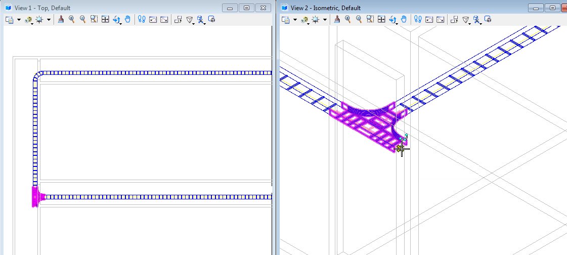
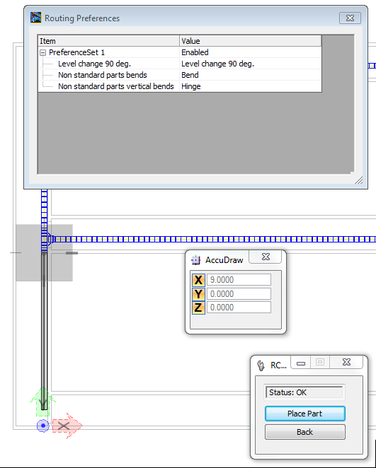
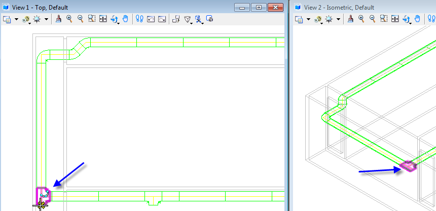
Select bottom end of Tee in Top view.
-
Add an 9m Straight part to that Tee, use AccuDraw.
-
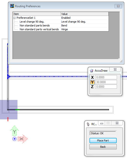
Move cursor to the right and use AccuDraw to add 30m straight
part.
-
Finish raceway generation with right mouse button.
-
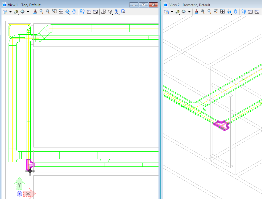
By this means the new raceway parts are made visible in the
drawing and the bend will be automatically generated.
-
Start the Display Manager.
-
Select Voltage Level Category entry MV , press right mouse button
and Hide.
-
Select Voltage Level Category entry LV, press right mouse button
and Show.
-
Use the function Raceway Router and press the Connect b9utton.
-
Select bottom end of Tee in Top view.
-
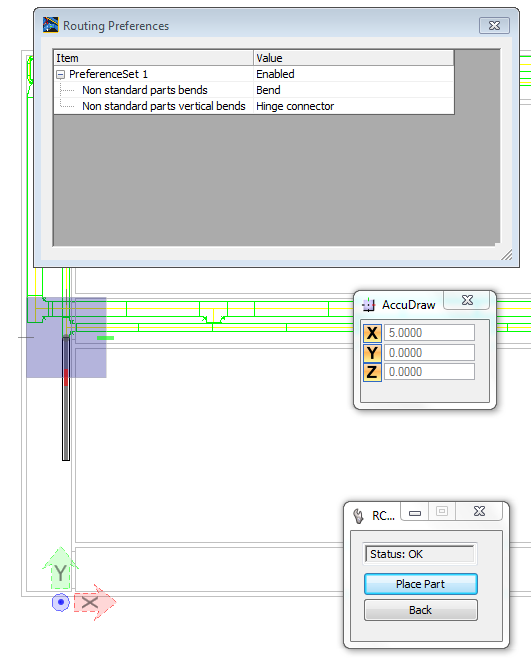
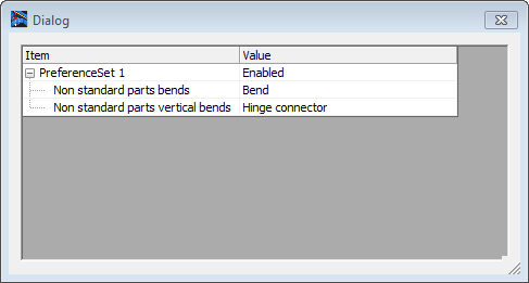
Set raceway settings in Dialog and insert part in design file (use
AccuDraw with X=5).
-
Select button Place Part.
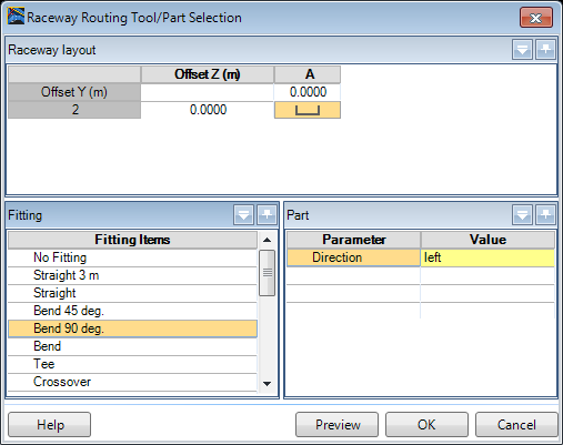
-
Select Bend 90 deg. to Direction left.
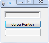
-
Use Cursor Position button.
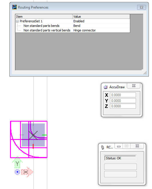
-
Select midpoint from Bend.
-
Next select the upper end from opening, set distance with AccuDraw
and option O to 0.2 and insert part.
-
Select button Place Part.
-
Select Tee to Direction left.
-
Use Cursor Position button.
-
Select midpoint from Tee.
-
Next select the upper Tee midpoint, set distance with AccuDraw and
insert the part.
-
Select button Place Par.
-
Select Bend 90 deg. to Direction right.
-
Insert part with the same distance as the Bend in the upper part
of the design file.
-
Select button Place Part.
-
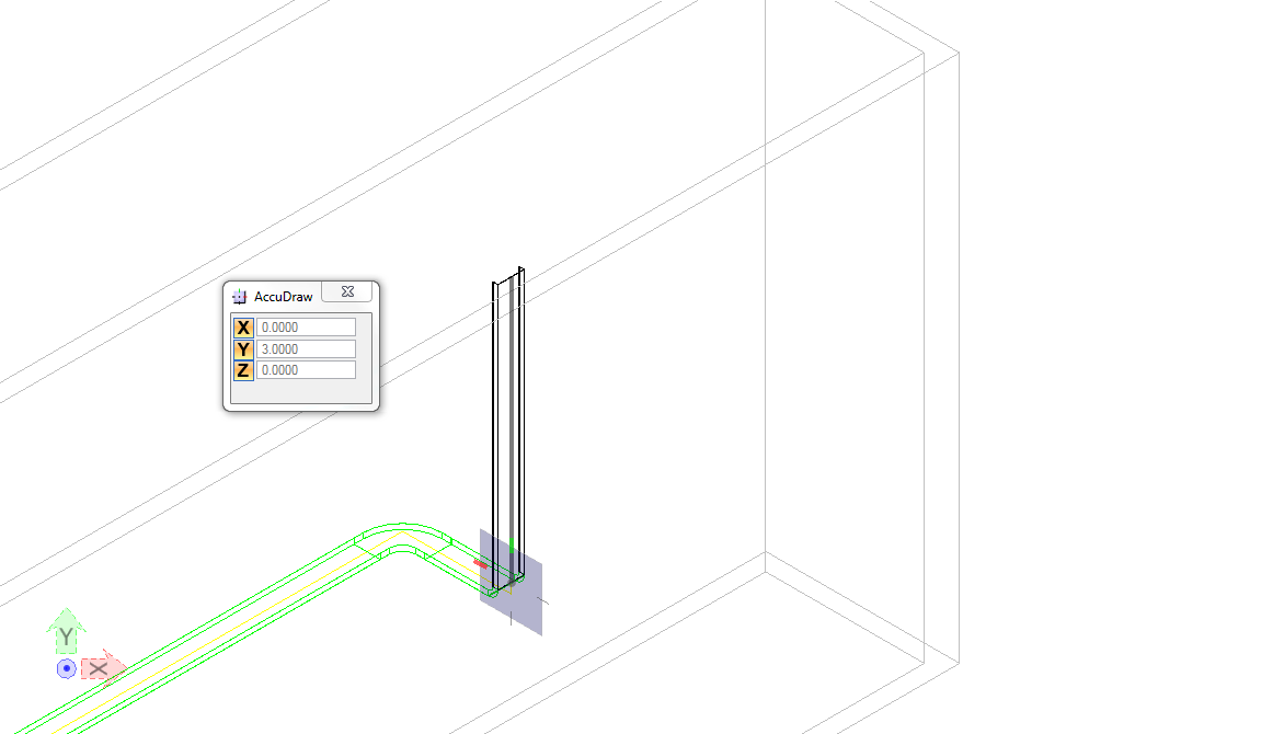
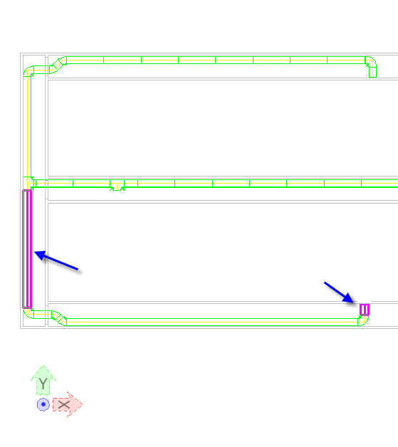
Select Custom vertical bend to Direction up, BendRadius 45 and
BendAngle 90.0.
-
Insert part in front of the wall.
-
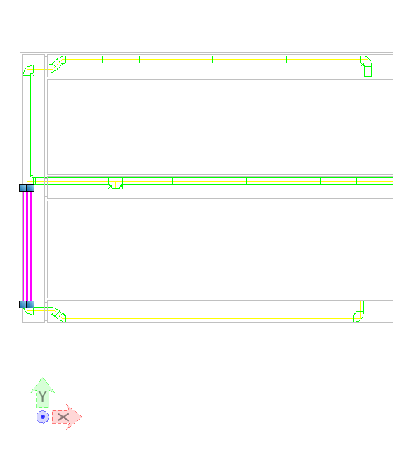
Continue raceway in 3D view e.g. Right Isometric with 3m up, use
AccuDraw.
-
Start the Display Manager.
-
Select Voltage Level Category entry LV, press right mouse button
and Hide.
-
Select Voltage Level Category entry CTRL, press right mouse button
and Show.
-
Use the function Raceway Router and press the Connect button.
-
Select bottom end of Tee in Top view.
-
Set raceway settings in Dialog.
-
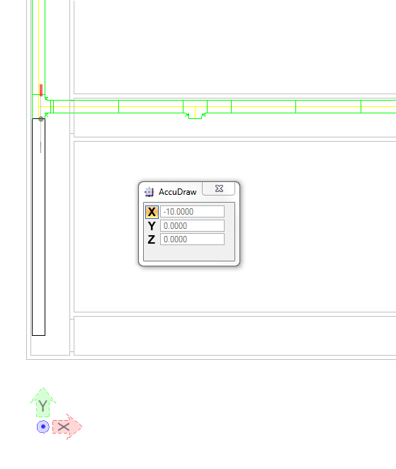
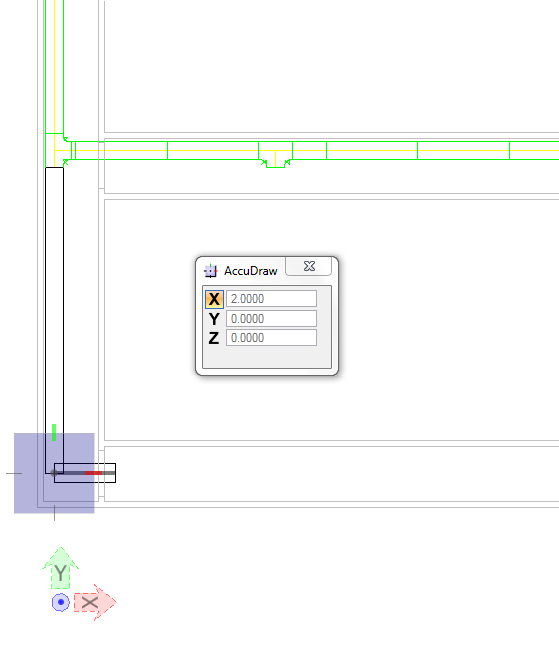
Insert parts in design file in south ( identical as in north) use
AccuDraw with X=10.
-
Continue with Y=2.
-
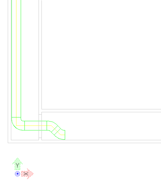
Continue with 45deg. Bend to the right and 45deg. Bend to the
left:
-
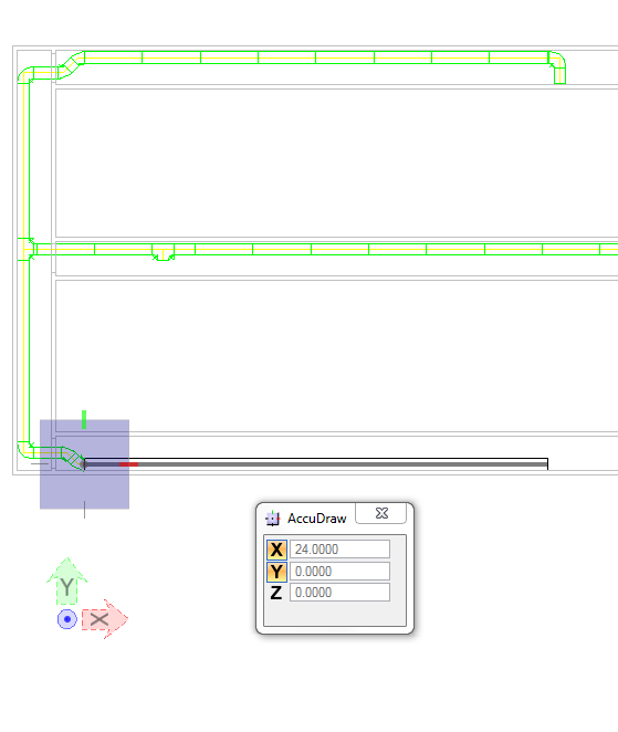
Continue with straight part X=24.00.
-
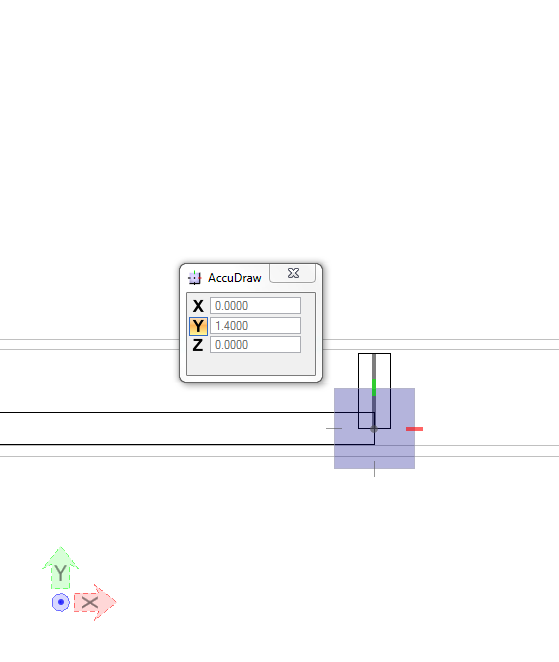
Continue with straight part Y=1.4.
-
Select one of the previous generated raceway parts, e.g. first
part.
-
Start the
Raceway
Properties function.
-
Set Voltage Level to CTRL.
-
Set following settings in Raceway Properties Manager:
- Dividers 1
- Divider / Section 1
[%] 50
- Divider / Section 2
[%] 50
- Layer to Layer 2
- Redundancy to
<none>
- Status to Design
- Max Capacity to medium
(75%)
- Accessories (Route)
<none>
- Accessories (Raceway)
<none>
- Voltage Level
<Section 2> LV
- Layer to Layer 3
- Redundancy to
<none>
- Max Capacity to medium
(75%)
-
Press button Extend Selection Set (routing) and select the first
and the last part of previously generated raceway parts: