Raceway Router
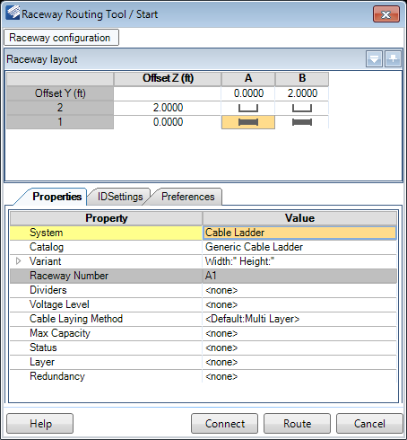
The Raceway Router enables you to interactively route raceway in your current design file. The tool supports multi-Routing (i.e, routing multiple raceway runs at the same time with a given horizontal and vertical offset).
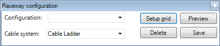
Raceway Configuration
Click the Raceway configuration icon at the top of the dialog to display the following drop down with options to define the Configuration and Cable system:
| Setting | Description |
|---|---|
| Configuration | When you setup a new configuration, you can enter a name for the configuration and save it to be reused later. Any previously saved configurations will be listed in the drop down list. |
| Cable System | The list will display all of the cable systems currently defined in the project. To define the system to use however, you will need to select the System from the Properties tab (See Below). |
| Save UDA | This button saves a new UDA configuration (defined in the Properties section) or changes to an existing UDA configuration. |
| Setup Grid | This icon displays the Setup Grid dialog, which enables you to define the basic layout (number of rows and columns) for the raceway. Once this is completed, you can use the Raceway Layout grid (shown below) to define the properties for the raceway components included in the grid. |
| Delete | Deletes the selected configuration. |
| Save | Saves the current configuration setup for future use. |
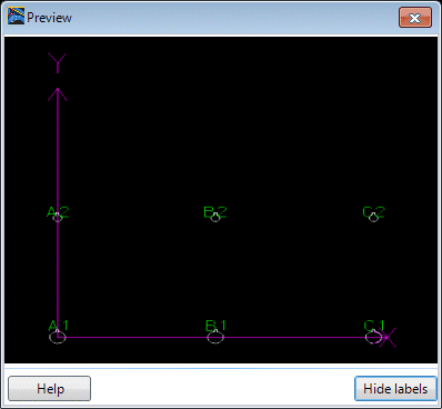
| Preview | Displays a preview of raceway arrangement as shown
below:
The Hide Labels icon toggles the display of the labels, which correspond with the Column/Row in the Raceway Layout grid. |
Raceway Layout
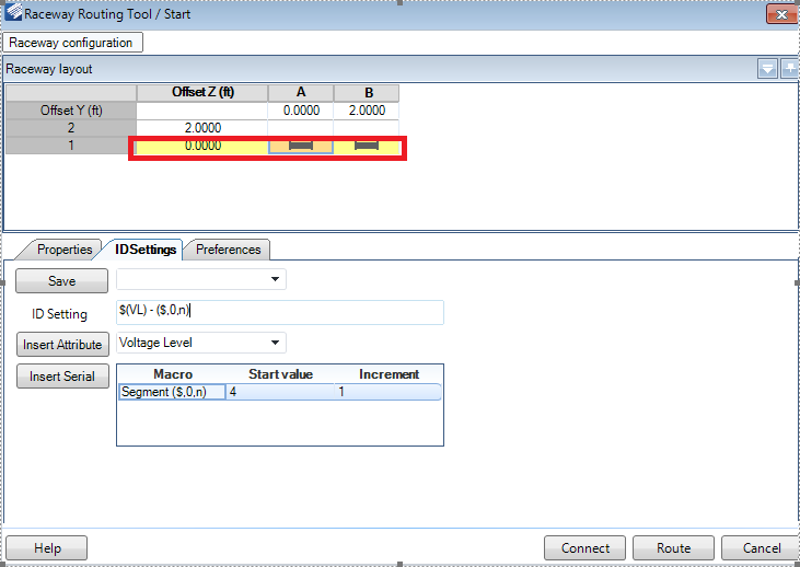
The Raceway Layout section display the raceway configuration as it was defined in the section above and allows you to define the Property/Preference values for the raceway components.
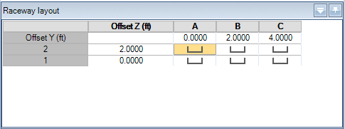
Click in a grid cell and use the Raceway Properties section to define the component properties. Each cell can contain different size raceway components with unique property values. You can also copy a component from one cell and paste it into others, which will copy the property values as well.
The Offset values define the spacing between the raceway components and the value typed directly into the field.
Raceway Properties
| Setting | Description |
|---|---|
| System | Select the type of Raceway system to be routed from the list. The following systems are included in the list: |
| Catalog | Select a catalog to use from the drop down list. |
| Variant | Define the size of the raceway/conduit component here. A cable tray size is defined as Width x Height while conduit is sized by the diameter. |
| Raceway Number | This number corresponds with the column and row of the raceway layout. For example Column A, Row 1 would have a Raceway Number of A1. |
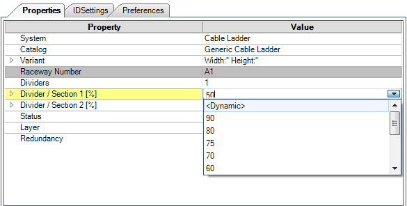
| Dividers | If the raceway is to be divided into different sections, define a number of dividers to use here. |
| Divider/Section [%] (OPTIONAL) | If the raceway contains dividers, then these fields
display letting you define the percentage of space each divided section will
occupy. A pick list provides commonly used capacity percentages so that you can
quickly set the capacity.
The <Dynamic> option is designed to automatically calculate the size of the sections created by the divider in order to allow the maximum number of cables to be routed. When the <Dynamic> option is chosen the
system will begin routing assuming that the first section has 100% available.
|
| Voltage Level | Select a voltage level from the drop down list: |
| Cable Laying Method | Select the method of laying the cable from the
following list of options. This determines the routing configuration for the
cable inside the raceway/conduit.
Refer to the Cable Laying Methods section for details on each method. |
| Max Capacity | The Max Capacity determines how much of the raceway/conduit area can be occupied with cables. |
| Status | Define the status for the raceway from the following list: |
| Layer | Select which layer the raceway will be modeled on from the drop down list. Raceway components have default layers assigned by default. If a layer is defined here, it acts as an override to the default layer. |
| Redundancy | When redundant systems need to be run, this option
allows you to label the system as such. By default, there are three redundancy
labels:
Additional Redundancy labels can be added in the Raceway Specifications/Raceway Categories tab of the Setup > Options dialog. |
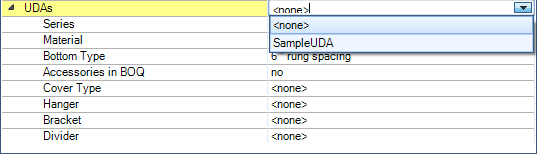
| UDAs | The UDAs (User Defined Attributes) section provides a list of predefined UDAs for the selected catalog. The UDAs field contains a drop down list of defined UDA configurations. A new UDA configuration can be defined by clicking in the field and manually entering a name. Once a new UDA configuration is created, you are able to define settings for the attributes and save the configuration for future use in the Raceway Configuration section defined above. |
| Accessories (Route) | This options allows you to define the spacing and size of the supports for the raceway/conduit system. Select an option from the drop down list. |
| Accessories (Raceway) | Select raceway accessories (dividers, brackets, covers etc.) to be included in the Raceway from the drop down list. |
ID Settings
| Setting | Description |
|---|---|
| Save | The Save option can be used to save and reuse any commonly used macros and share them with all project participants. All ID Settings configurations are stored in the metadata folder in the CFG_RacewayLabels.xml file. |
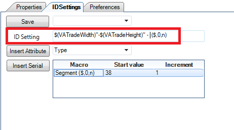
| Insert Attribute | This is used to insert any available UDA associated
with the selected catalog. A list of all UDAs associated with the catalog can
be viewed in the
UDA section of the
Create New Raceway Catalog tool.
Users can add different characters between attributes to display units or indicate separation between attributes. |
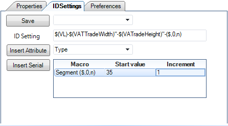
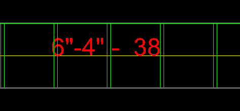
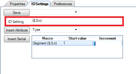
| Insert Serial | Insert Serial is used to insert a unique serial
number for each raceway section. After the raceway layout is placed, it is
automatically adjusted to the first available number. User can manually
overwrite the start value.
By using a macro ($,0,n), the serial number will be generated taking into account the start value and increment. |
Raceway Preferences
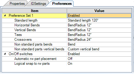
The Preferences tab allows you to define preferences to use when routing raceway systems, such as type of bends, bend radius, as well as certain placement preferences. These preferences are saved if you define and save a configuration in the Raceway Configuration section of the dialog. (See above)
| Setting | Description |
|---|---|
| PreferenceSet 1 | When enabled, the preferences defined are used when routing the raceway system. When disabled, the default catalog preferences are used. |
| Straight length | Select the preferred Straight Length raceway component to place. |
| Bend (30, 45, 60 and/or 90 deg.) | Define the preferred bend radius to use if a horizontal bend is placed. |
| Vertical Bends (30, 45, 60 and/or 90 deg.) | Define the preferred bend radius to use if a vertical bend is placed. |
| Tees | Define the bend radius to be used if a tee is placed. |
| Crossover | Define the bend radius to be used if a crossover is placed. |
| Non standard parts bends | Defines what action is taken when a non-standard bend angle is encountered while routing a raceway system. |
| Non standard parts vertical bends | Defines what action is taken when a non-standard vertical bend angle is encountered while routing a raceway system. |
| On/Off Switches | Toggles whether the two switches described below activated or ignored. |
| Automatic rw part placement | When this is enabled and you route components, Bentley Raceway and Cable Management will automatically recognize intersections where Tees or Crosses are needed and automatically place the correct fitting. |
| Logical snap to rw parts | When this is enabled and you are connecting to an existing component, it will automatically snap to the correct location on the end of the component without having to select a specific snap point. |