Connectors Gallery
Used to place HVAC Connector components.
Accessed from the HVAC ribbon:
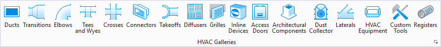
The following gallery displays which can be left floating or docked to the drawing area.
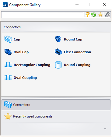
The following table shows the component options in the gallery along with the key in syntax. Selecting a tool from one of the placement galleries activates the Place Component dialog. The generic placement settings, along with the unique set of dimensional and data properties provide the core workflow used to accurately position equipment components in the model.


Component Placement
Select an option from the Connectors gallery.You are prompted to pick a location for the cap component. Pick a point in the drawing to display the Place Component dialog. This dialog is common to all HVAC components and allows you define a component's physical parameters as well as general properties before placement. The dialog remains open throughout the placement process.
In the Place Component dialog's Settings tab, select a placement point to determine which port serves as the placement point for the component.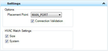
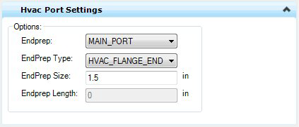
| End Prep | Defines which port to apply the EndPrep Type, Size and Length values to. You are able to define different values for each port if desired. |
| EndPrep Type | HVAC_Flange_End, HVAC_MALE_END, HVAC_Female_End, HVAC_Plain_End |
| EndPrep Size | Enter a size for the EndPrep Type. |
| Endprep Length | Enter length for the selected EndPrep Type. |
While enter/changing values in the fields, the component is dynamically updated in the drawing so you can see the changes before placing the component.
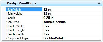
An example of the design conditions tab (Connector) is displayed below: Once the component parameter and property values are defined you are prompted to select a placement location for the component. Pick a location and click a data point. If the component requires a direction pick, use the mouse to rotate the component into the correct position then click a data point. Right-click to complete the process.