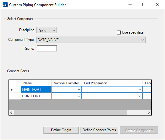
The Custom Piping Component Builder (displayed below)
lets you create custom components from geometric graphics which either exist in
the active drawing (for a one time use), or have been drawn in a .CEL file,
which can be saved and re-used in other design files within the same project.
The Custom Piping Component Builder provides for two different
workflows for creating custom components:
- Creating User Components
for one time usage: this workflow will allow the user to define and create
custom components in an active design file; life cycle and usage of the
component will be specific to the design file it was created in.
Note: To create a one
time custom component, an active pipeline must exist in the drawing.
- Create Custom Piping
Component for Re-use: this workflow will allow the user to define, create and
store components in a library (i.e. cell library). which is then placed using
the
Place Component from Cell option. These custom components
will be re-usable in any design file within the same project.
| Use Spec Data
|
If this option is selected, the Connect
Points properties are populated using the information from the active
specification for the selected Component Type.
If more than one record for the Component Type
exists in the spec, then the Spec Record Selection dialog displays prompting
you to select a specific record to use for the component.
For example: If a Ball Valve is selected as a Component
Type with this option enabled, then the Connect Point fields will be populated
using the information from the specification.
The current Nominal Diameter value from the
Standard Preferences dialog is used for the component.
Note: This
option is not applicable when creating a Custom Support.
|
| Discipline
|
Select from either Piping or Support. This
determines what kind of component is created.
|
| Component Type
|
Lists the available component types in the
schema to choose from.
|
| Rating
|
Input a rating for the component. This field
is disabled when the Use Spec Data option is selected as the Rating value for
the selected component is taken from the spec.
|
| Connect Points
|
The Connect Point information grid is enabled
displaying editable entries of Connect Point Information. The number of entries
(rows) reflects the number of ports as defined in the schema for the selected
Component type. (For Example, a Four Way Valve will have four port entries
etc.)
Note: Note that
the values in the Connect Points fields are only editable when the Use Spec
Data option is not enabled. Otherwise the fields are populated using defined
values from the active specification.
- Name: Reflects
the name(s) of the ports defined for the selected Component Type.
- Nominal
Diameter: Select a value from the list if not using the current spec values.
- End
Preparation: The list will contain all of the available values for the selected
component type.
- Facing: List
will contain the available facing option for the selected component type.
Note: This
option is not applicable when creating a Custom Support.
|
| Define Origin
|
Click to pick a point on the component to use
as an origin point.
|
| Define Connect Points
|
You will be prompted to pick a point and
define a direction for each listed port.
Note: This
option is not applicable when creating a Custom Support.
|
| Create Component
|
Creates the component and displays the Modify
Component dialog, allowing you to define additional property values for the
component as necessary.
|
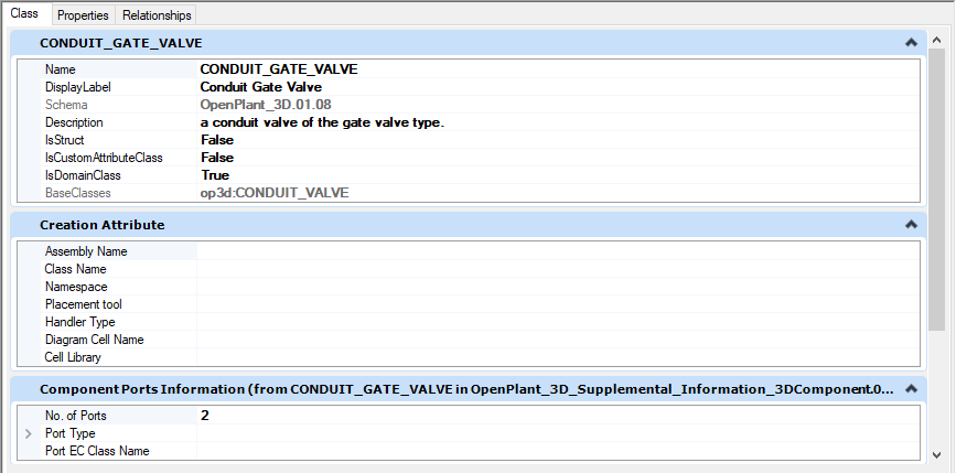
Creation
Attribute
In order for a custom component to be able to be created
from native elements, the Creation Attribute must be defined for the type of
custom component that is to be created. Most components will have this
attribute defined by default but there are some which do not. When trying to
define a custom component using one of these component types the following
message will display in the component center and the component creation will
not be able to proceed until this attribute is defined:
'Creation Attribute' is missing on the component class in
schema
The Creation Attribute is defined for a component class in
the
OpenPlant Project Administrator using the Class
Editor. The following schemas must be loaded into the Class Editor to add the
Creation Attribute:
OpenPlant_3D.01.08.ecschema.xml
Supplement the schema with the following:
OpenPlant_3D_Supplemental_Information_3DComponent.01.08.ecschema.xml
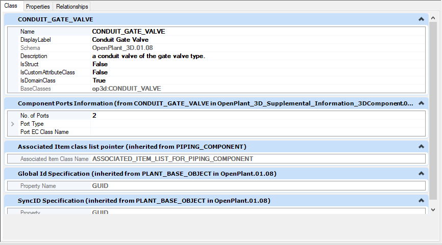
Find the component class which needs to have the Creation
Attribute added such as the CONDUIT_GATE_VALVE shown below:
Add a new custom attribute as shown:
Once the Creation Attribute has been added and saved, you
will be able to create a custom component using this component type.
Note: Refer to the Class
Editor help for complete details on adding custom attributes to a component
class.
Key-in:
Mechaddin
Create CustomPipingComponent