When placing a piping component in
OpenPlant Modeler
, a dialog displays allowing you to define placement information
for the component. The placement dialog has two command buttons described below
as well as expandable tabs in which you can define placement behavior as well
as component properties for the component to be placed.
The dialog is a common dialog which is placed with all
Piping/Trayline/
HVAC type components. Accessed when:
- User selects a component
from any of the Piping, Trayline, HVAC or Support component galleries.
Note: Equipment
type components have a separate dialog which assists you in defining the size
parameters of the equipment.
Note: This dialog is
remains open during placement of the component and will remain open until the
command is terminated. This allows you to place more than one instance of the
same component if desired.
| Setting | Description |
|---|
| Match Properties
|
Prompts you to select an existing component in the
model and will place a component with properties matching the selected
component, thus overriding the default settings in the Standard Preferences
dialog. (For example, if the main size is set to 10" in the Standard
Preferences dialog and you click Match Properties and select a 4" tee in the
model, the program will pick up the properties of the 4" tee and place a 4"
component.)
Note: The component
does not have to be connected to the existing component.
|
| Select Component Instance
|
This option displays the Spec Selection grid for
component that have more than one spec record. Once a spec record is selected,
normal placement procedures will apply. If you want to change the spec record,
click on the button again to display the grid.
|
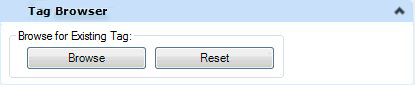
The Tag Browser is only available when:
- Working with a WorkSet
associated with a PlantSight project
- You have a local PID
drawing attached as a reference to the current model.
Either of the options above lets you access the tags from
your
OpenPlant PID drawing and use them when placing
3D components. When you select a piping component for placement, the following
Tag Browser section is displayed at the top of the Place Component dialog:
| Setting | Description |
|---|
| Browse
|
Displays the
Tag Browser allowing you to search through a list of
existing tags that are available for the component class being placed. If you
select an existing component tag number, the new component being placed will
inherit the component properties associated with the selected tag number. You
can opt to rename the tag number for the new component and still retain the
inherited properties if desired.
|
| Reset
|
The button will reset the tag number to its original
value.
|
Note: When placing
components with the 2D tags, the relationship data associated with the tag must
be defined in the model before the tag can be used. If not, then a message
dialog listing the conflict will display.
Click here on information on the possible conflicts that
may encounter when placing components with 2D tags.
Settings
Tab
This tab provides options relating to the placement
points of piping components.
| Setting | Description |
|---|
| Placement Point
|
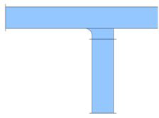
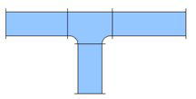
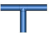
When placing a length of pipe, the dialog displays
as shown above. To determine the placement point for the pipe, use the mouse to
select either the center point (as shown) or one of the four corners on the
pipe end in the provided bitmap shown below.
Note: The bitmap
above displays when placing Pipe only, the Placement Point drop down enables
with the following options:
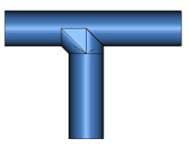
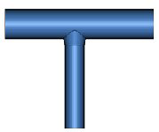
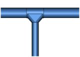
When placing fittings, branching components and other
piping components other than pipe, the Placement Point drop down enables with
the following options:
- Main_Port
- Run_Port
- Branch_Port
(Branches Only)
- Other
|
| Elbow Type (Elbows Only)
|
When placing an elbow, this drop down list displays
allowing you to specify the type of elbow to be placed.
|
| Apply Slope Settings (Applies only When Placing Pipe)
|
The Apply Slope Settings will use the slope
settings defined in the
Apply Slope dialog while routing pipeline components. This
allows the designer to dynamically visualize the affect a slope value on a
pipeline during the designing phase and to possibly make corrections to avoid
clashes with other items.
When the Apply Slope option is set, if using the
AutoFitting mode, the Allow Misaligned Fittings option will automatically
enable and allow rigid bend components, such as 90 deg elbows to be placed if
the misalignment is within a set tolerance. By default the tolerance is 10
degrees (+5, -5 degrees on either side of the bend.)
|
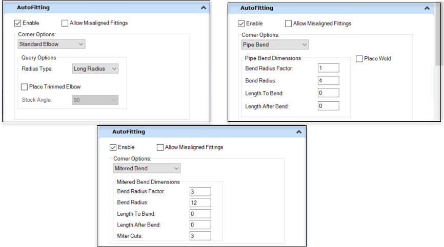
AutoFitting Tab
(For Piping Components Only)
The AutoFitting tab shown provides options to define the
placement behavior when placing pipe lengths which include bends.
| Setting | Description |
|---|
| Enable
|
Check this option to enable the AutoFitting method
for placing components. When enabled, the options section becomes available to
define the bend/elbow options. If disabled, then a bend or elbow will not be
placed at angles when routing pipe.
|
| Allow Misaligned Fittings
|
When this option is checked, rigid fittings, such as
45 and 90 degree elbows, will be allowed when placing bends using the
AutoFitting method when the bend is within a 10-degree range of misalignment
(+5, -5 degrees on either side). This value can be changed by modifying the
configuration variable (OPM_MISALIGNMENT_ALLOWANCE=10)
Note: The Allow
Misaligned Fittings option is automatically enabled when the Apply Slope
Settings is selected in the Settings tab.
|
| Corner Options
|
Select either the Standard Elbow, Pipe Bend or
Mitered Bend option from the drop down list to determine how elbow/ bends are
automatically placed when routing a pipe run. Each option provides a different
set of additional fields to help define how the elbow or bend is selected and
placed.
|
| Standard Elbow Options
|
This option places an elbow when routing a 90deg.
angle in a pipe length. When selected, a set of Query Options (shown above) are
displayed to define how to select the correct elbow for placement:
- Radius Type: Select
from either Long Radius, Short Radius or 3R.
- Place Trimmed
Elbow: When enabled, a trimmed elbow is placed.
- Stock Angle:
Used to define the angle of the trimmed elbow. Select one of the available
angles from the field.
|
| Pipe Bend Options
|
The Pipe Bend option places a pipe bend instead of
an elbow where there is a bend with an angle which doesn't match any of the
elbows in the spec. When selected it display a set of fields used to define the
bend dimensions as shown:
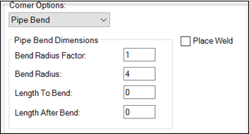
Place Weld: When enabled, a weld symbol
will be placed at the connection points of the bend.
|
| Mitered Bend Options
|
The Mitered Bend option places a Mitered bend
instead of an elbow. You can place Mitered Bend as an Autofitting during Pipe
routing. Also similar to Pipe Bends, you will be able to place mitered bend at
any angle while auto routing. When selected it display a set of fields used to
define the bend dimensions as shown:
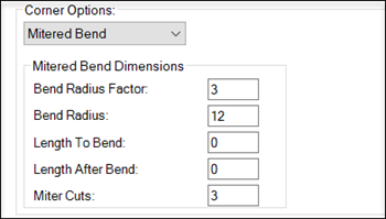
Bend Radius Factor And Bend
Radius:- These two properties are directly related to each other.
This means that any change in one property reflects in the other property's
value. The values are calculated as below:
If the Bend Radius value is changed
Bend Radius Factor = Bend Radius / Nominal
Diameter
If the Bend Radius Factor value is changed
Bend Radius= Bend Radius Factor x Nominal
Diameter
Bend Radius value is mapped with Pipe Bend Radius
property and Bend Radius Factor is mapped with Bend Point Radius Factor of
ECClass.
Miter Cuts:-Enter an integer
value. If a double value / decimal number is entered, the number before the
decimal point is taken as the value of the cuts.
Angle Limits:-The mitered
bend angle property is Bend Point Angle. MITERED bend angle property value low
limit is set to 30 degrees which can be changed by defining
OPM_MIN_ANGLE_FOR_MITERED_ELBOWS config variable. The upper limit is set to 90
degrees which can be changed through OPM_MAX_ANGLE_FOR_MITERED_ELBOWS config
variable. These limits are also defined in drawscript of the mitered bend.
Autofitting can draw mitered bends between these
angles.
Note: Autofitting
validates the shape and type of component for mitered bends. It can only be
drawn between two linear components. For example, if you try to attach a pipe
with a reducer at 90 degrees, the mitered bend will not be drawn even if the
mitered bend is selected from auto-fitting options. This is because the reducer
is a fitting type component.
|
| Slope Settings (For Piping Components Only)
|
When the apply slope settings option is enabled,
this section allows you to define the slope settings before placement.
Select the method of defining the slope from the
drop down list as shown:
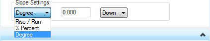 Define a value for the method
selected. Each method will display a different value field in which to enter
the slope value. Define a value for the method
selected. Each method will display a different value field in which to enter
the slope value.
- Rise/Run: Determines
the slope by how much the run will rise over a given distance. For example,
with a 6/12 slope the pipe would rise 6' for every 12' of run.
- % Percent: Uses a
percent as a slope value. Using the example above, a 6/12 slope is considered a
50% slope.
- Degree: Uses a
defined degree angle to determine the slope.
Once the slope is defined select the direction of the slope
as either Up or Down from the list to the right.
|
Properties
Tab
This section displays a variety of property tabs which
expand displaying editable fields to define the property values of the
component. An example is shown below:
| Setting | Description |
|---|
| Component Name
|
Enter the tag number for the component.
|
| Operating Conditions
|
Represent real life conditions that a component will
most likely be exposed to.
|
| Design Conditions
|
Specific working conditions the component class was
intended to operate in.
|
| Model Server Info
|
Enter Design State for the component.
|
| General Info
|
Properties defining general physical properties of
the component being placed.
|
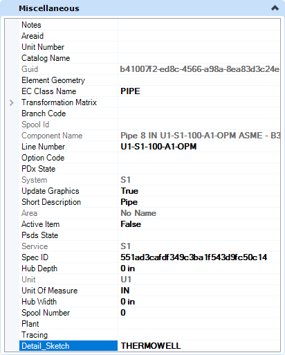
| Miscellaneous
|
Miscellaneous properties pertaining to the
component.
|
Detail
Sketches
The Detail_Sketch property has been added to the
OpenPlant3D schema at the DEVICE level, meaning you can define a detail sketch
for a specific component to be included when generating an isometric using the
OpenPlant Isometric Manager. This property can be defined when initially
placing the component, or when modifying one. It is located in the
Miscellaneous tabbed section as shown below:
Enter the name of the detail sketch cell into the field to include
it when generating an isometric.
By default, the OpenPlant Isometrics Manager will look to
the default cell libraries which are included with install, one of which is
named Detail_Sketch.cel. The cell libraries are located in the Cell directory
for each isometric style in the project. For example, the IFC style can be
found in the following directory:
...\OPModeler_Imperial\DataSet\Isometrics\Styles\IFC\Cell\
If you define a detail sketch cell file in the
Detail_Sketch property field, that cell must be included in one of the cell
libraries or the isometric process will not find it causing an error. If you
have existing detail sketches defined in a cell library, you can copy that file
into the Cell directory for the isometric style and the Isometrics Manager will
find it.
Click Here for a detailed
procedure on how to add a detail sketch to a cell library and include it on an
isometric.
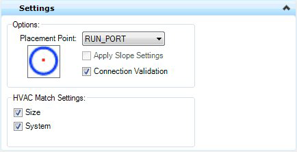
HVAC Specific
Placement Options
When placing HVAC components, the following HVAC specific
options are displayed in the Place Component dialog.
In the Settings tab, select a placement point to determine which
port serves as the placement point for the component. The options in the
Placement Point list will vary depending on the component being placed.
(Available Placement Points for Duct are Main_Port and Run Port.)
| Setting | Description |
|---|
| Placement Point
|
When placing fittings, branching components and
other piping components other than pipe, the Placement Point drop down enables
with the following options:
|
| Apply Slope Settings
|
**Applies to Piping components ONLY**
|
| Connection Validation
|
Connection validation performs a validation check
based on the joints definition and connection criteria set in the configuration
variables. If the connecting components fail this check these are not
connected. If this option is turned off, a valid joint is created between
component even if they do not satisfy the connection criteria.
|
| HVAC Match Settings
|
These options, when enabled, will automatically
adopt the Size and System of an existing component in the drawing when you are
connecting to that component. The current values for these settings as defined
in the Standard Preferences dialog will be overridden.
For example, if you have an HVAC system HVU-HVS-101
set in the Standard Preferences dialog, then you place a new HVAC component to
a component on a different system (HVU-HVS-102), using the Match Settings
options, then the new component will be placed on the HVU-HVS-102 system and
will adopt the same size as the existing component.
|
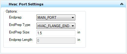
HVAC Port
Settings
The HVAC Port Settings tab allows you to define the End
Preparations for the ports on the component to be placed. An example is shown
below:
| Setting | Description |
|---|
| End Prep
|
Defines which port to apply the EndPrep Type, Size
and Length values to. You are able to define different values for each port if
desired.
|
| EndPrep Type
|
HVAC_Flange_End, HVAC_MALE_END, HVAC_Female_End,
HVAC_Plain_End
|
| EndPrep Size
|
Enter a size for the EndPrep Type.
Note: This is
disabled if HVAC_PLAN_END is selected.
|
| EndPrep Length
|
Enter length for the selected EndPrep Type.
|
Note: As you define values
for the Port Settings, the changes are dynamically updated in the drawing as
you tab to the next field.
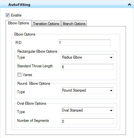
AutoFitting
Settings
When placing duct, it is suggested to enable the
AutoFitting method which will automatically recognize and place components
where a change of direction, or a transition is included in the placement
process. The AutoFittings settings will define the type of component that will
be automatically placed in these situations. Use the tabs displayed below to
define the placement options for Elbows, Transition and Branch components using
the AutoFitting method.
| Setting | Description |
|---|
| Enable
|
When enabled, all the settings provided in the above
AutoFitting interface will be applied when placing the duct components. If the
check box is disabled, the AutoFitting rules from the AutoFittingRules.xml file
will get applied and all the controls from AutoFitting tab will be disabled.
|
Elbow Options
| Setting | Description |
|---|
| R/D
|
The value entered in R/D textbox will decide radius
for the elbows placed using the AutoFitting method.
|
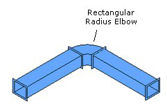
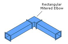
| Rectangular Elbow Options
|
Type: Select either Radius Elbow or Mitered from the
list. This determines which type of elbow is placed using the AutoFitting
method.
Standard Throat Length: Determines the throat length of the
mitered elbow.
Vanes: Toggles the placement of vanes in the elbow.
|
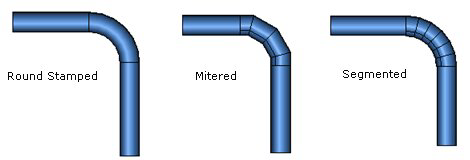
| Round Elbow Options
|
There are three types of Round Elbow types available:
- Round Stamped
- Mitered
- Segmented
Placement of the Round Stamped elbow is dependent on its
availability in the selected spec. If the size is not available, the AutoFit
function will search for a Mitered/Segmented elbow in the spec and place
accordingly.
|
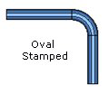
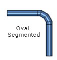
| Oval Elbow Options
|
The Oval Stamped type is the only available.
However, depending on the Number of Segments defined, either a stamped or
segmented elbow will be place.
- Number of Segments
= 0 (Stamped elbow placed)
- Number of Segments
>1 (Segmented elbow placed)
|
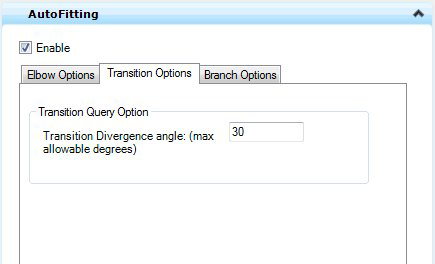
| Setting | Description |
|---|
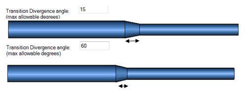
| Transition Divergence Angle
|
For Transitions (Reducers) should provide option to
define maximum allowable divergence angle. If values entered for this exceed
this limit transition length should be recalculated according to max allowable
angle.
|
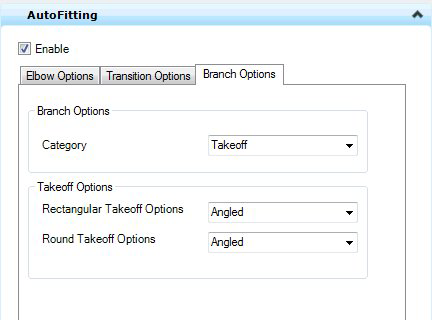
| Setting | Description |
|---|
| Branch Options
|
Two options are available as branch options:
Each option provides a different set of options to
choose from for placement as detailed below.
|
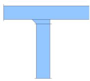
| Takeoff Options
|
If the Takeoff branch option was selected, then the
following takeoff options are available for placement:
- Rectangular Takeoffs
- Round Takeoffs
|
| Tee Options
|
When the Tee branch option is selected, the
following set of Tee options are available for placement:
- Rectangular Tee
Options
- Radius Tee
- Square Throat
Tee
- Round Tee Options
|
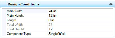
Design
Conditions
The Design Conditions tab provides fields to define the
physical parameters of the component. The field options will vary depending on
the type of component being placed.
Required Values
The Rectangular duct option requires values for the Main
Width and Main Height. These fields will by default use the current values
defined in the
Standard Preferences dialog, but the values defined in the
Design Conditions fields will override the default.
Note: If placing a
predefined component from the spec such as Round or Oval duct the fields in
this tab will be read only.
Key-in:
MECHADDIN
PLACE COMPONENTBYNAME