2D to 3D Integration
OpenPlant 2D to 3D integration lets you compare components in an OpenPlant PID drawing with equivalent components in an OpenPlant Modeler drawing, as well as place components from a referenced OpenPlant PID i-model from the navigation tree in the Explorer dialog. This functionality lets you exchange tag information as well as perform consistency checks to ensure continuity between function and physical design.
This functionality operates by opening an OpenPlant Modeler session and attaching an existing OpenPlant PID i-model (Created in OpenPlant PID) as a reference file.
Offline Configuration Variable
If you are working with a WorkSet provisioned to an iModel on PlantSight and try to browse tag data from an attached PID.dgn.idgn drawing the following configuration variable must be set otherwise when you try to create a pipeline from the Consistency Checker tree, the relationship data will not be defined correctly. Also, when you access the Tag Browser when placing an equipment component, the browser will display the data from PlantSight instead of from the attached drawing.
OPM_USE_OFFLINE_2D3D_ON_CONNECTED_MODE = True
This variable needs to be set using the Configuration Variables dialog.
Attach the i-model
When an i-model is attached to a dgn, OpenPlant Modeler will search through all of the classes in the i-model against the class list defined using the following variable located in the project specific Modeler.cfg file found in the following location:
C:\ProgramData\Bentley\OpenPlant CONNECT Edition\Configuration\Workspaces\WorkSpace\WorkSets\<Workset>\Standards\ModelerBy default, the PID_DOCUMENT class is defined as all of the components in OpenPlant PID inherit from this class.
OPM_2D3D_IDENTIFIER_CLASS_LIST = PID_DOCUMENTHowever, you can add more classes to the list by using separators as shown below:
OPM_2D3D_IDENTIFIER_CLASS_LIST = PID_DOCUMENT|OP_CLASS_A|OP_CLASS_B|...If an instance of a class found in the i-model is listed under this configuration variable file then the i-model is considered to be a 2D i-model and the 2D3D consistency checker is launched.
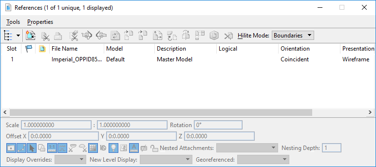
 icon to display the Attach
Reference dialog. From here, you can select the i-model to attach.
icon to display the Attach
Reference dialog. From here, you can select the i-model to attach.
- If you are logged into ProjectWise, the Attach Reference dialog will display the available i-models which are stored in the ProjectWise project. If you are referencing an i-model stored in a local, directory, you can Cancel out of the ProjectWise dialog and select the i-model from the local directory.
- Click the Display
 button in the References dialog
to turn/off the display of the attached reference.
button in the References dialog
to turn/off the display of the attached reference.
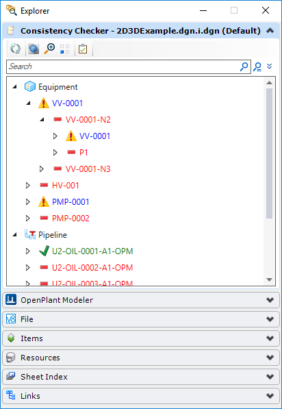
Consistency Checker Tree
When acceptable OpenPlant PID i-models are attached, a Consistency Checker tree is added to the standard Explorer Dialog which will display components from the OpenPlant PID i-model. Multiple i-models can be attached simultaneously displaying multiple Consistency Checker trees. Each component will be color coded and supplied with a consistency status indicator. are successfully placed in the
model.
are successfully placed in the
model.
 are not placed in the model.
 are placed in the model, but have
inconsistencies between the 2D and 3D components.
are placed in the model, but have
inconsistencies between the 2D and 3D components.
Custom Attribute Setting
When an i-model is attached to a 3D drawing, OpenPlant looks for certain specified 2D properties to compare with matching 3D properties. The properties used for the comparison, and subsequently used when placing the components, are defined in the OpenPlant_Supplemental_ConsistencyChecker schema located in the Workspace\Projects\Schema directory. Open the schema in the Class Editor (included with the OpenPlant Project Administrator install) and set the following custom attribute to True.IS_SHARED_PROPERTY
This setting will ensure that the property is included when performing the consistency check, and also copied to the 3D component during the placement.Place Components using 2D Tags
Components can be placed using the 2D tags either directly from the Consistency Checker Tree, or using the Tag Browser, which is accessed from the component placement dialog.
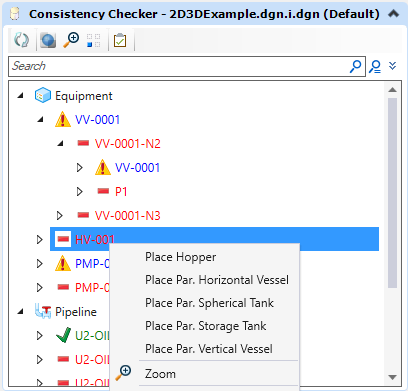
Place a Component from the Consistency Checker Tree
When you right click on a component in the tree, a pop up menu displays with a list of possible 3D classes to place in the model.
- Components with duplicate tags cannot be placed. For example, if a component in the tree is displayed in green text with a green check mark it already has been placed in the model and the tag cannot be re-used.
- When importing a 2D pipeline, the NOMINAL_DIAMETER value of the current pipeline in OpenPlant Modeler is automatically set as the diameter of the imported pipeline.
- Component with the same EC Class if they exist in the OpenPlant 3D Schema.
- EC Subclasses from the OpenPlant_3D schema.
- If an EC Class or Subclass if found, then a list of peer classes (classes on the same level) in Openplant 3D.
Using the SPEC_ID
When certain components are placed in a OpenPlant PID drawing, the spec selection of the component has already been performed using the Spec Record Selection dialog. When, you place a corresponding 3D component from the Consistency Checker Tree, OpenPlant Modeler recognizes the SPEC_ID for the component and does not display the Spec Record Selection dialog during the placement process. OPM will use the SPEC_ID to identify and place the component.
This following configuration variable controls this behavior:OPM_INCLUDE_SPECID_IN_QUERY
Nozzles
Nozzles are allowed to be imported from an OpenPlant PID and placed in an OpenPlant Modeler as Freeform nozzles.
If a 2D nozzle being imported has a size value defined in OPPID, then it will pop up grid selection dialog against that size while placement and that size will be automatically set in Standard Preferences dialog.If 2D nozzle has no size value, then it will inherit the size currently set in Standard Preferences dialog.
Areas
OpenPlant Modeler supports the placement of various types of areas in a model including the following: To add an area to the model, use the following key-in:mechaddin makevolume DESIGN_AREA
mechaddin makevolume UTILITY_AREA etc...The following custom attributes were added to allow the transformations of areas not originally supported:
-
OPM_2D3D_TRANSFORM_MAPPING: This mapping is used to define mappings between
OpenPlant PID and
OpenPlant Modeler
classes or properties. By default, this attribute has been
defined to allow the following
- Import of PLANT_AREA from OPPID to OPM: adding this custom attribute on PLANT_AREA class in the OpenPlant_Supplemental_Consistency_Checker schema and mapping it to an appropriate OpenPlant Modeler class. OPM class must not have CREATION_ATTRIBUTE defined on it and the IS_GRAPHICAL property of the OPMS ModelServer Class Map custom attribute defined in OPMS supplemental schema should be set to 'False'.
- Map the DESIGN_SIZE property of class MAJOR_PIPING_NETWORK_SYSTEM to NOMINAL_DIAMETER property of PIPING_NETWORK_SYSTEM class: This mapping converts the string type value of the source property to double type value of the target property when creating the target class instance in OPM.
- OPM_2D3D_ASSOCIATION_MAPPING included in the OpenPlant_3D_Supplemental_Modeling schema, this attribute can be used to map an OPM association and its relationship to OP association and relationship. (For example: If you define an association with the class LOGICAL_AREA using the relationship AREA_HAS_NAMED_ITEM and want to map this association to OP PLANT_AREA and PLANT_AREA_HAS_NAMED_ITEM.)
Use the Tag Browser to select a 2D tag for the component
Another method is to select the desired 3D component from one of the component galleries to display the Place Component dialog. When a valid i-model is referenced to the current 3D model, the Tag Browser section is added to the Place Component or Place Equipment dialogs when you select an option from one of the component taskbars. When you click the Browse button, the Tag Browser dialog opens displaying the available 2D tags which match the class of component you are trying to place. The tags are listed under the i-model node in the dialog. Multiple i-models can be attached to a model and will display as separate trees in this dialog. When you select a tag from the dialog and click OK, the tag number and its inherent properties will populate the placement dialog for the component. Here you have the ability to modify any property values if desired, including the tag number.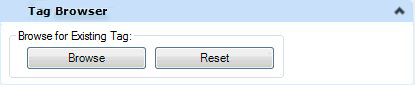
Once tag number has been selected, normal placement procedures will apply per the component class being placed.
Consistency Checker Reports
You can generate a report comparing the components between the referenced 2D drawing and the active 3D model using the following key-in:
MECHADDIN CCREPORTIn the Consistency Checker Report View there is an option to update an existing 3D component's properties when 2D components that have been modified in OpenPlant PID. When the Consistency Report is generated, the changes are recognized and displayed in the Report Viewer allowing the user to see exactly what property values have changed before synchronizing.
Possible Conflict Dialogs
There are a few message dialogs that may display if there is a conflict between the 2D tag information you are trying to associate with a new 3D component.
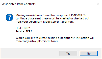
Missing Associated Items
This prompt lets the user know that there are missing associated items that must be created prior to placement. In the CC tree this will perform the action and then start placement, but in the Tag Browser which is already in an active placement tool, placement is cancelled and user must restart placement manually just as if they were to manually alter standard preferences during placement.
Pipeline Conflict
This prompt displays when you attempt to place a component with a different pipeline than the one currently defined in the Standard Preferences dialog.
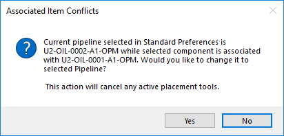
- Yes - When selected, the component's pipeline will be set to active. If they have an active placement tool i.e. using the Tag Browser, then it will cancel placement, but if placing from the Connectivity Checker tree, it will activate the pipeline and then begin placement.
- No - When using the Tag Browser, selecting No will nullify the selected component tag. This will allow you to either, select another tag from the Find Component dialog, place normally, or Cancel. If you select No when placing from the Consistency Checker tree, placement will not change the pipeline and no placement will begin.
Modifying Components
If modifying a component using the Tag Browser, selecting components from the Find Component dialog is similar to when placing a component. However, the Find Component dialog is filtered by selected component's size instead of the value in the Standard Preferences dialog.
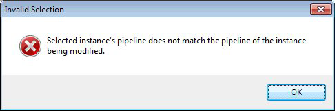
If you attempt replace an existing component with a component associated with a different pipeline, the following message displays and the data for selected component will not replace the existing data in the modify component dialog: Clicking OK cancels the selection and returns to the Modify Component dialog. From there, you can either click Browse and select another component from the Find Component dialog, or close the Modify Component dialog.