Project Configuration
Provides options for
you to define default project settings to use when generating Isometric
drawings from Isosheets.
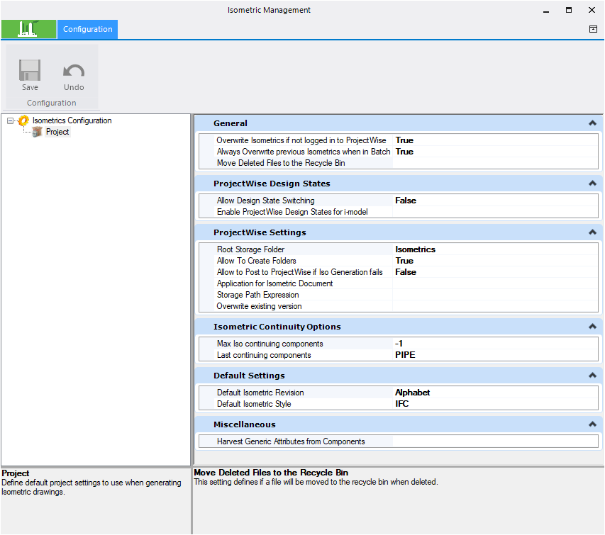
Accessed from the main ribbon.
The options are grouped in expandable tabs as shown below:
| Setting | Description |
|---|---|
| General |
Overwrite Isometrics if not logged into PW — This
option determines how isometric files are created when you process an iso sheet
from the IsoSheet Grid, more than once. Select from either a True of False
value.
Note: Please note
that if you have already created multiple copies of an isometric (as mentioned
in the example above,) and then change the value to True and reprocess the same
iso, the system will reset the output file naming to the default drawing name
without the .r00x version number. Old versioned files are moved to the
recycle bin when the new iso is processed. So if you want to keep these files,
make sure to create a backup first.
|
| ProjectWise Design States | Allow Design State Switching — This option sets design file switching. |
| ProjectWise Folder Settings | Root Storage Folder — Defines the root storage
folder for project isometric drawings. Click on the Browse button within the
field to display a Folder Selection dialog listing the directory structure for
the active datasource.
Allow To Post to
ProjectWise if Iso Generation
fails
— This option permits posting iso to
ProjectWise in the event iso generation
fails.
Application for Isometric Document — When posting an
isometric to
ProjectWise, this field allows you to apply
a specific application for the isometric. For example, if Bentley Navigator is
assigned to an isometric when posted to
ProjectWise, the next time it is opened from
ProjectWise, it will be opened in Bentley
Navigator.
Storage Path Expression — Enables you to define a storage path convention for the iso sheets. Click the Browse button to display the Isometric Storage Path Expression Editor which enables you to define a text and property string to use as a storage path convention.
|
| Isometric Continuity Options | Max Iso continuing components — The continuing
components give the user a reference of how the current isometric sheet
connects with another drawing. The Max Iso continuing components option
determines how many components from the connecting drawing will be displayed.
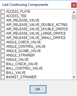
Last continuing components — Enter a component class
directly into the field or click the browse button to display the following
dialog allowing you to select which continuing component(s) to search for.
|
| Default Settings | Default Isometric Style — Select an iso style from one
of the following options:
Default Isometric Revision — Allows you to define the default Isometric Revision setting in either alphabetic or numeric terms. Click the Browse button to display the Revision Settings dialog used in defining the revision format. |
| Miscellaneous | Harvest Generic Attributes from Components — In this field you can specify an attribute that is only available in the component tags to become available as drawing attribute. In the process of generating the iso, the program will scan the component tags to find the given attribute. If found, it will be written to the intermediate file in the TEXTNODES section. |
| Save | Saves the changes made in the dialog. This button is disabled until a change is made. |
| Undo | Deletes the latest change. This button is disabled until a change is made. |