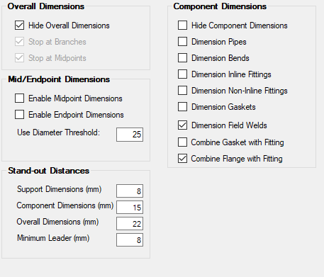
| Overall Dimensioning
|
The Overall Dimensioning section provides general
options which apply to all components in an isometric.
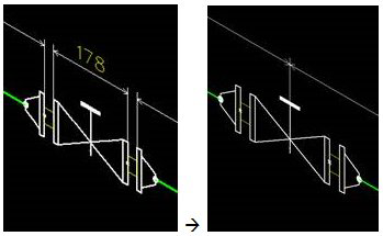
- Hide
Overall Dimensions — Do not show component level dimension.
- Stop at
Branches — Break the overall dimension at branch points e.g. Tee,
Olet, cross etc.
- Stop at
Midpoints — Break the overall dimension at dimensioned midpoints.
This option is only effective when midpoint dimensioning is enabled.
|
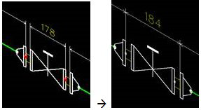
| Mid/Endpoint Dimensions
|
Midpoint dimensioning dimensions to the midpoint of
an inline component (or the spindle point in so far available). A threshold
value specifies the diameter below which mid-point dimensioning is enabled. The
components eligible for mid-point dimensions are inline components for which
IE_TYPE contains "VALVE", "FITTING" or "INSTRUMENT". For flanged fittings the
dimension skips over the gaskets.
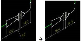
Endpoint dimensioning is an extension of midpoint
dimensioning but for non-inline flanged components like tees and elbows or
flanged assemblies. It allows for dimensioning over a flanged connection.
- Enable
Midpoint Dimensions — Enable mid point dimensions.
- Enable
Endpoint Dimensions — Enable end point dimensions. This option is
only effective when midpoint dimensioning is enabled.
- Use
Diameter Threshold — This specifies the nominal pipe diameter above
which mid/endpoint dimensioning is disabled. The value can be specified in
decimal inches or millimeters. The conversion factor used is 25.
|
| Standout Differences
|
Specifies the distance from centerline to dimension
line for each of the dimensioning levels in millimeters.
- Support
Dimensions (mm) — Level 1 - Supports (mm): Defines distance between
support and dimensioning line in (mm).
- Component
Dimensions (mm) — Defines distance between component and
dimensioning line in (mm).
- Overall
Dimensions (mm) — Defines distance between component (or group of
components) and dimensioning line in (mm).
- Minimum
Leader (mm) - Defines the minimum length of the leader line for
standout dimensions.
|
| Component Dimensioning
|
Component level dimensions provide the basic
dimensioning for fabrication.
Note: Please note
that some of these options may conflict with one another. As you select an
option (or hover the mouse over it) information regarding any rules which apply
to the functionality of the option is displayed at the bottom.
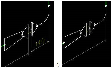
- Hide
Component Dimensions — Do not show component level dimension.
- Dimension
Pipes — Force pipes to be individually dimensioned.
- Dimension
Bends — Force bends to be individually dimensioned.
- Dimension
Inline Fittings — Force inline components to be individually
dimensioned.
- Dimension
Non-Inline Fittings — Force non-inline components (Tee, cross,
elbow) to have each leg individually dimensioned.
- Dimension
Gaskets — Force gaskets to be individually dimensioned.
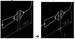
- Dimension
Field Welds — Toggles On/Off the dimensioning of field weld
positions.
- Combine
Gasket with Fitting — Overrides the Dimension Gaskets option. Only
available for inline fittings.
- Combine
Flange with Fitting — When checked a non flanged fitting port
connected to a flange is interpreted as an assembly joint. Overrides the
"dimension inline/non-inline fittings" setting.
|