Gasket tick marks provide a visual aid for interpreting dimensions
that end on a gasket. In the Style.cfg file for each isometric style, define
the settings in the table below to control the display of the tick marks.
lThese files are located in the following directory (using the IFC style as an
example):
C:\...\Workspaces\WorkSpace\WorkSets\OpenPlantImperial\Standards\Isometrics\styles\IFC\config
The following section has been added to control the display of gasket
tick marks:
# to show gasket tick marks set to 1
DimTickShow = 1 # weight for gasket tick marks
DimTickWeight = 3 # Cheap gasket dimensioning, Gasket are
dimensioned to one side at most
DimTickAll = 0 # Dimension witness line offset for centerline
for a given endprep
DimLift_FL = 10
DimLift_IF = 10
See the table below for descriptions on the options:
| Setting | Description |
|---|
| DimTickShow
|
1 - Enables the display of tick marks.
0 - Disables the display of tick marks.
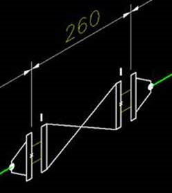
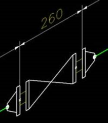
When enabled tick marks are placed where only one side of the
gasket has a dimension waypoint as shown:
|
| DimTickWeight
|
The numbered setting defines the thickness of the tick mark
(Example: DimTickWeight = 3 is the default)
|
| DimTickAll
|
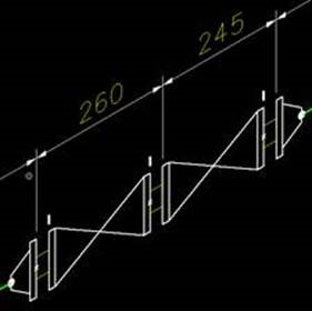
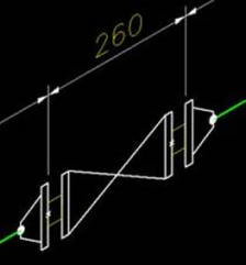
DimTickAll=1: Every gasket that would have normally have
dimension way points on both sides will now get only one. (See Below)
DimTickAll=0: Turns off this option.
Note: Please note
that this is only applied when the Combine Gasket with Fitting is enabled.
|
| DimLift_FL/DimLift_IF
|
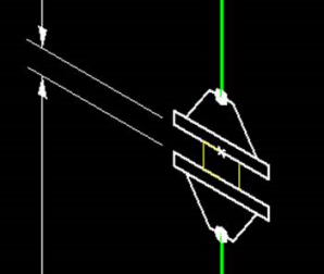
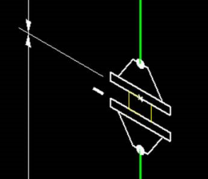
In this same section are variables to define an offset for
dimension extension lines for flanges and gaskets. This value offsets the
extension line from the element as shown below:
Ordinarily this offset is defined in the Microstation Dimension
Styles dialog and this is still the default method of defining dimension
styles. The following variables however, can be defined for each isometric
style to control how the extension line is offset for flanges and gaskets:
DimLift_FL = 5.5
DimLift_IF = 5.5
Note: The values for
the offsets are defined in millimeters.
|