Place Facility
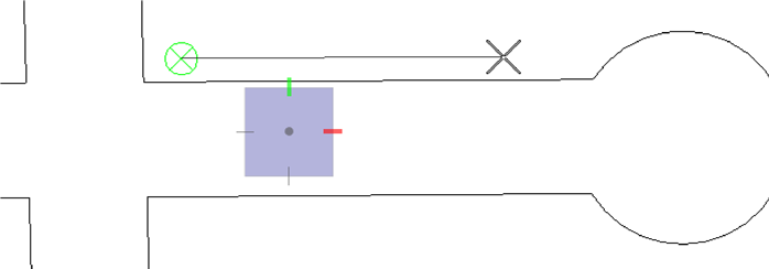
If a strand resource has been loaded, clicking the Place Facility command will prompt the user to ‘left click’ two points in the map view to determine the starting angle for the first strand or trench distance. After setting the angle the following dialog will display:
- Click SKIP to skip the placement of a pole or ped and place a NULPED cell at the current location. This cell must be included in the cell library and can be created as a small circle, slash, or another symbol.
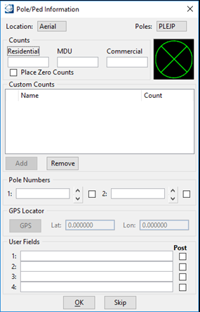
- Set the location of your pole/ped - Aerial, Underground, Buried, Riser.
- Set the Pole or Ped type.
- The Custom Counts section allows the user to place customized House Counts. (See House Count Cells under Edit a Strand Resource file.)
- Key in the number of counts for Custom, Residential, MDU, and/or Commercial. If the ‘Place Zero Counts’ box is checked and a zero is entered in for the count, a house count symbol with a zero is placed on the map.
- Key in the pole numbers. It is possible to enter two different numbers to identify a single pole. Pressing the up or down arrow increments or decrements the pole number accordingly. Selecting the Post check box next to a pole number indicates the information posted on the map.
- User fields are available for use. Any information entered in these 4 fields can be posted on the map.
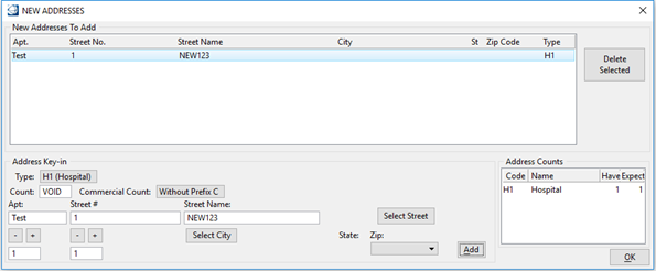
- Click OK when finished. The New Addresses dialog box opens, allowing you to enter and place new addresses on the map and in the database.
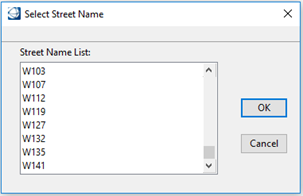
- From the New Addresses dialog box, click Select Street to open the Select Street Name dialog box.
- Key in the street name or choose it from the Street Name list.
- Key in the street number, city, zip code, and apartment.
- Click Add to add addresses in the New Addresses To Add list. To delete an address, highlight it in the list and click the Delete Selected button.
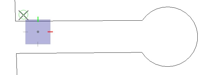
- Click OK when completed. The pole or ped is on the cursor.
- Place and accept the pole or ped.
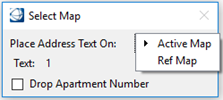
- Place the House/MDU/Commercial text as it is on the cursor.
- Place the address text as
necessary.
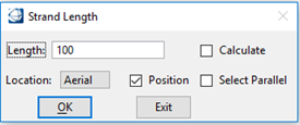
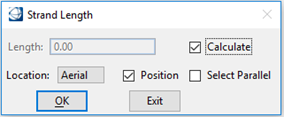
- The Strand Length dialog box opens.
- Enter the length of the
strand.
Note: If using segmented length for underground, use a + between the lengths. For example, 125+30+100 indicates that there are three segments between two peds totaling 255 feet. A Cell named NULPED is inserted between the segments. The nulped cell must be created if it does not exist in the cell library and can be created as a small circle, slash, or another symbol.
- Change the Location type as necessary so the BOM report reflects accurate information.
- Activate the Position check box to repositioned or window-center the active view with the pole or ped location.
- Click OK to proceed with the strand placement. If Reset is selected to change the position, the endpoint of the line is on the cursor. A radius is displayed indicating the keyed in distance. If using Calculate distance, you will need to specify the location of the strand endpoint.
- Position the distance text by moving the cursor above or below the line. Accept the position or Reset to change the position. Press data to accept the placement.
- Position the text and accept it. To have the distance text on the cursor for unrestricted placement, press Reset. This returns you to the beginning of the Stranding process. After placing the last pole and being prompted for a strand distance length, click Exit.
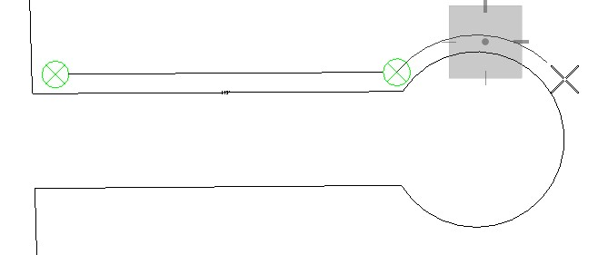
Place New Facility Parallel to a Road
- From the Facilities Tab, select Facility in the Placement section.
- Click Reset to select the line or arc for parallel placement.
- Select a line on the map.
- The Pole/Ped information box opens.
- Enter the necessary information and click OK to proceed.
- A pole/pedestal is on the cursor.
- Moving the cursor moves the pole/pedestal parallel to the road with an offset specified in the strand setup.
- Click Data to place the pole/pedestal on the map.
- Click Reset to rotate the pole/pedestal or Data to accept the angle.
- The Strand Length dialog box opens.
- Select Place Parallel to place the strand parallel to the road.
- Click OK to proceed with the strand placement.
- Select a line/arc on the map for the strand parallel placement.
- Click Data to accept the
line/arc. If using Calculate distance, you will need to specify the location of
the strand endpoint.
If entering strand distance in the Strand Length dialog box, the strand end point is drawn automatically on the map. Click Reset to change the endpoint position.
- Position the text and accept it. To have the distance text on the cursor for unrestricted placement, press Reset. This returns you to the beginning of the Stranding process.
Place New Facility Parallel to a Cul-de-sac