| Labeling Style |
- None - No Labels are generated for display. Use this setting to turn off labeling for the selected feature.
- By Layer - Provides options to create a simple label definition.
- Thematic - Provides options to create a complex label definition and blends the labeling capabilities of the layer style with thematic mapping. In addition to creating text from property data, the symbology of the text elements can be based on user-defined classes. The interface for defining the classes is the same as thematic mapping for layers of type Point-Text.
See the Thematic mapping section for details on how to create thematic mapping classes.
After classes have been generated, the text string to be placed is defined in the Labeling section. Other parameters can be set and changed as needed.
|
| Global Settings |
- Initialize with Text Style - Sets the text parameters to match those of the selected text style. All the fields can be further edited for custom formatting.
- Scale - The scale factor applied to the text string.
|
| Labeling |
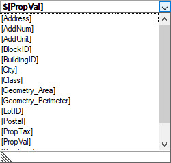
- Text String - The actual value of the label displayed in the view. It can consist of a static text that you enter to prepend or append the feature property. Available feature properties are accessed from the pull down list and are entered into the Text String field when selected. Feature properties are enclosed in square brackets.
Complex labeling can be created by adding text and functions to the Text String entry. For example, this following line of code will produce the label below. The \n causes a newline to be inserted into the labeling.
Value: $[PropVal]\nArea: [XFM.Round([Geometry_Area],2)] sq. m

- Origin - Specifies the label origin relative to the feature instance.
- For point features, the origin is the same point calculated by the Element Origin snap.
- Linear features provide the following Origin options:
- Element Origin - The same point calculated by the Element Origin snap.
- Element Mid - The same point calculated by the Element Center snap.
- Element End - The opposite endpoint that would be calculated by an Element Origin snap.
- Options for Polygon features:
- Element Origin - The same point calculated by the Element Origin snap.
- Element Center - The same point calculated by the Element Center snap.
- Offset X,Y and Z - Specifies the offset from the point specified by Origin. The offset could be typed or extracted from a property.
- Orientation - Specifies the orientation of the labeling.
- Fixed - Places the labeling at the orientation specified by Text Angle in the Formatting section.
- Element Relative - Places the labeling on the same angle as the element being labeled. If there is an angle specified in the Text Angle setting of the Formatting section, then that value will be added to the angle determined by the element.
- (*) Collection Occurrence Type - Applies to all collection types (linear, point and polygon).
- One Per Instance - Places one label for the entire feature collection instance.
- One Per Part - One label per part within a polygon feature collection instance. A part could be a single polygon or grouped hole. This setting applies to polygon collections only.
- One Per Element - Places one label for each element within a feature collection instance.
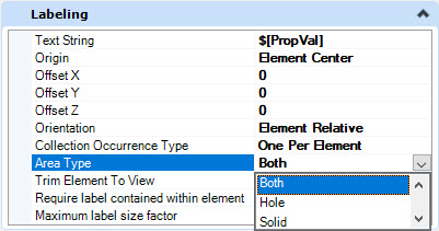
- (*) Area Type - Applies to both collection and non-collection polygon classes only.
- Both - The label is placed for both solids and holes.
- Hole - The label is placed for holes.
- Solid - The label is placed for solids.
- (*) Trim Element to View - Applies to both collection and non-collection linear classes only. If set to True, then the element to label is trimmed to the view boundary and the label is positioned on the trimmed element. The default value is False.
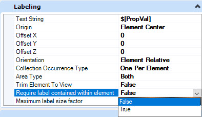
- (*) Required label contained within element - Applies to both collection and non-collection polygon classes. If set to True, then the ranges of the element to label and the label are compared. If label range is within the element range then the label is drawn. The default value is False.
- (*) Maximum label size factor - Applies to linear and polygon classes that are collections or non-collections. If a non-zero value is set, then a size factor is computed from the ranges of the element to label. If the label size factor is greater than the specified value, then label is not drawn. For example, if the specified value is 0.7, then to draw the label, the label range size must be less than or equal to 70% of the element to label range size. Double value. Default value is 0.0.
|
| Text |
These options set the common MicroStation text options. See the MicroStation documentation for details.
|
| Geometry |
Text Angle - Specifies the angle that the text will be placed on. It is affected by the Orientation selection from the Labeling group of options.
|
| Formatting |
These options set the common MicroStation formatting options. See the MicroStation documentation for details. Fixed size sets the size for the text relative to the screen. If Fixed Size is False, the values specified are in master units. If fixed size is True then the values specified are relative to the screen. The text size will not change when zooming in and out.
|