| Type Name
|
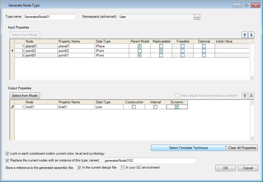
Used to input a name for the generated node type.
Note: Choose the
name it carefully. It is helpful to number the name for each design iteration
consecutively so that later it is easier to tell which node is the most recent.
|
| Namespace (advanced)
|
Used to define a namespace for the generated node
type. The default namespace is
User.
- Select Namespace –
clicking
 (browse) opens the
Namespaces, where you can select a desired namespace. (browse) opens the
Namespaces, where you can select a desired namespace.
|
| Input Properties
|
Contains controls used to define the inputs of the
generated node.
-
Select from Model — Used to select the
inputs of the generated node in the Graph or Geometry window. When selected,
you can select nodes in the Graph or the geometry windows.
- Inputs table —
Populates upon selection of an input from the model in the following columns:
- Node – Displays
the input node name.
- Property Name –
Used to enter a name for the input property. The inputted value will appear as
the input port on the generated node.
- Data Type –
Allows you select which data type the input port will accept.
- Parent Model –
Sets the selected input as the parent model.
- Replicatable –
If the generated node is to be replicated it is necessary to check
Replicatable for those inputs that
will be able to accept lists and single input values alike.
- Freeable – When
on, restrictions to the input parameter are removed allowing the input to
manipulated freely.
- Optional – When
on, the input parameter becomes optional. Usually the state of this setting is
inherited from the input nodes you select.
- Initial Value –
Displays the value of the selected input at the time of creation.
Once the inputs have been selected, the existing node icons
in the Graph are highlighted with colors to indicate the inputs and outputs. A
blue outlined node represents an input, while green represents an output. If a
node is outlined in blue and green, it has not been explicitly selected but is
an inferred input based on the initial selection.
|
| Output Properties
|
-
Select from Model — Clicking Select from
Model under the
Input Properties controls starts the
selection of input nodes. In most cases it is not necessary to select the
outputs because they are automatically selected based on the input selection.
- Outputs table —
Populates upon manually selecting an output from the model or appears those are
linked with input selections, in the following columns:
- Node – Displays
the output node name.
- Property Name –
Used to enter a name for the output property. The inputted value will appear as
the output port on the generated node.
- Data Type –
Allows you select which data type the output port will provide.
- Construction -
Allows you to make a geometry node of the generated node hidden by default, but
visible when the
Construction is selected.
- Internal -–
When on, the output node becomes permanently invisible but it still is being
calculated internally.
- Dynamic – When
on, the generated node's output will be dynamically updated by default.
- Hide
outputs that are marked as Internal — Enabled when Internal in
Output Properties is checked. The
output is not displayed for the node.
- Up/Down
Arrows — Moves the currently selected Input/Output property up or
down within the list.
|
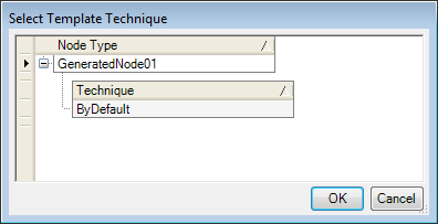
| Select Template Technique
|
When selected, opens the
Select Template Technique dialog opens.
You can select a techniques from available template
techniques and apply by clicking OK .
|
| Clear All Properties
|
Clears all input and output properties in the dialog
so you can start over.
|
| Lock-in each constituent node's current color, level,
and symbology
|
When on, symbology of each constituent node type is
maintained within the generated node.
|
| Replace the current nodes with an instance of this
type, named:
|
When on, the constituent input node is renamed using
the name inputted in the provided field.
|
| Store a reference to the generated assembly file:
|
Used to control where the generated node is stored.
- In the current
design file – When on, the generated node is only available in the active DGN.
- In your GC
environment – When on, the generated node is available in any DGN you create.
|
| OK
|
Accepts all changes and generates the new node type.
The generated node type appears in the Node Types dialog in the
Generated category.
|
 Used to define the node input and
output parts in Generate Node Type dialog, that
defines the input and output properties of a node and associate a namespace to
it.
Used to define the node input and
output parts in Generate Node Type dialog, that
defines the input and output properties of a node and associate a namespace to
it.