Grid Systems Manager
 Used to set the shape, size,
placement, and appearance of all elements and components contained in a grid
system.
Used to set the shape, size,
placement, and appearance of all elements and components contained in a grid
system.
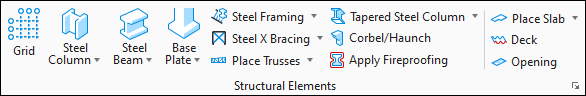
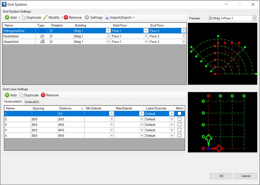
Grid systems functionality offers a column grids utility in which a building can have multiple grids in transient Grid Systems (orthogonal, radial and Sketch grids) applied to specific floors or ranges of floors. The Grid Systems dialog contains settings for adding, copying and removing grids, inserting grid lines, manipulating grid line spacing, rotating grids, and setting grid line symbology and other preferences. Additionally, you can manage Sketch grids in transient working environment mode and create, manipulate sketch grid lines which do not restrict the traditional definition of either orthogonal or radial grid systems.
In addition to creating grids, the Grid Systems functionality can import grid system information originating in external applications such as RAM Structural System, and reconstitute them inside OpenBuildings Designer. Both the ISM import tools (New from ISM Repository and Update from ISM Repository) can be used for this. Also, new grid systems and changes to existing (imported or natively) grid systems can be exported via ISM export tools (Create ISM Repository and Update ISM Repository).
Grid System Settings toolbar
| Setting | Description |
|---|---|
| Add | Used to add new grids to the grid system. The new
grids can then be manipulated using the available Grid System Settings.
|
| Duplicate | Used to copy existing grids. The copies appear in the row below the selected grid definition. |
| Modify | Used to modify orthogonal and radial grids orientation using the Move and the Rotate tools, accessed using the option. For Sketch grids, grid lines should be created before using the Orientation command. |
| Remove | Used to delete existing grids from the grid system list. Selected grid definitions are removed using the Remove or by pressing <Delete>. |
| Settings | Opens the Grid System Settings dialog where default settings for how Grid Systems are presented, labeled and dimensioned are managed. |
| Import/Export | Used to import from and export to Grid Systems definitions through XML for exchanging grid information with your project team. |


Grid System Settings table
Used to manipulate grids. Selecting a grid row activates the settings for that grid.
| Setting | Description |
|---|---|
| Name | Used to enter a name for the selected grid. The name entered is the name associated with the graphic cell elements which contain the grid graphics. |
| Type | Displays the iconic illustration of the grid type. |
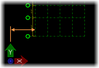
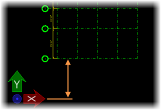
| X Offset | Sets the grid’s origin offset in the X direction
from the active coordinate system’s origin.
Note: X Offset is disabled by
default in favor of using the
Grid Systems Orientation controls for offsetting grids. If you prefer offsetting
grids from here, you can enable it by selecting
X Offset on the column header row's right
click menu.
|
| Y Offset | Sets the grid’s origin offset in the Y direction
from the active coordinate system’s origin.
Note: Y Offset is disabled by
default in favor of using the
Grid Systems Orientation controls for offsetting grids. If you prefer offsetting
grids from here, you can enable it by selecting
Y Offset on the column header row's right
click menu.
|
| Rotation | Sets the grid’s rotation from the active coordinate system origin. Positive values rotate the grid counter clockwise. |
| Building | Assigns selected building to Grid System definition from the list of buildings you defined in the Floor Manager where multiple Building definitions are set. |
| Start Floor | Sets the first floor to which the selected grid is applied. Grids can be applied to a range of floors or to a single floor. |
| End Floor | Sets the last floor to which the selected grid is applied. Grids can be applied to a range of floors or to a single floor. |
Grid Lines Settings toolbar
| Setting | Description |
|---|---|
| Add | Used to add new grid lines to selected grid definition. New grid lines appear at the end of the grid lines table with next incremental Label in Name. |
| Add/Modify | Appears in place of Add for Sketch grid definitions. Opens the Add/Modify Grid Lines toolbar toolbox that is used to create / manipulate Sketch grids. |
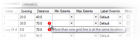
| Duplicate | Used to copy existing grid lines. The copies appear in the row below selected grid line in the table. Disabled for Sketch grid definitions. Duplicated grid lines inherit properties of the selected grid line. The alert message indicates the grid line at the same location, until you amend the Spacing and/or Distance value. |
| Remove | Used to delete existing grid lines from the grid lines table. Selected grid lines are removed using the Remove or by pressing <Delete>. |
Grid Lines Settings table
Used to manipulate grid lines. Selecting a grid line row activates the settings for that grid line.
| Setting | Description |
|---|---|
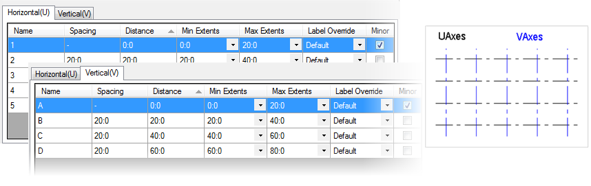
| Horizontal (U) | Vertical (V) tabs | Enabled when orthographic grids are selected from the Grid Line Settings table. |
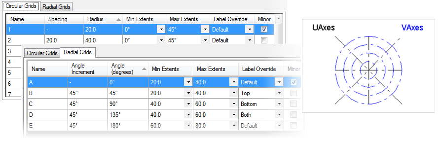
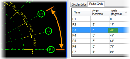
| Circular Grids | Radial Grids tabs | Enabled when radial grids are selected from the Grid Line Settings table. |
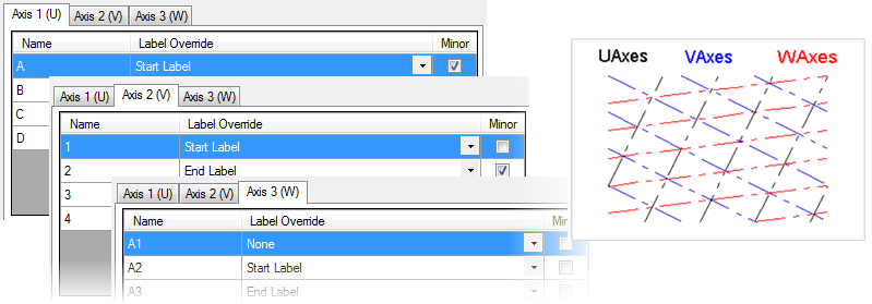
| Axis 1 (U) | Axis 2 (V) | Axis 3 (W) tabs | Enabled when Sketch grids are selected from the Grid Line Settings table. |
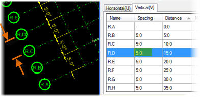
| Name | Used to enter the grid line label for the selected grid line. Follows the default Grid Labels scheme set in the Grid System Settings dialog. |
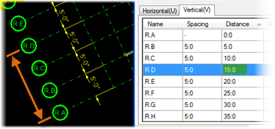
| Spacing | Enabled on the Horizontal(U), Vertical(V) and Circular Grids tabs. Displays and sets the distance or angle between the selected grid line and the preceding grid line on the grid lines table. Accumulated distances or angles (measured from the grid origin) are calculated and displayed in the adjacent Distance column. |
| Distance | Enabled on the Horizontal(U)/Vertical(V) tabs. Displays and sets the distance between the selected grid line and the grid origin. Values entered here override the Spacing value for the selected grid line only. |
| Radius | Enabled on the Circular Grids tab only. |
| Angle Increment | Enabled on the Radial Grids tab only. Sets the angle incremental value from previous grid line. |
| Angle (degrees) | Enabled on the Radial Grids tab only. Displays and sets the angle between the selected grid line and the grid origin axis. Values entered here override the Spacing value for the selected grid line only. Positive values rotate grid lines counter clockwise. |
| Min Extents | Select the intersecting grid line to determine the smallest extent for the grid line being changed. The value is set by selecting an option from the options available in the drop-down. |
| Max Extents | Select the intersecting grid line to determine the
maximum permissible extent for the grid line being changed. The value is set by
selecting an option from the options available in the drop-down.
The options under Min Extents are always smaller than the options in Max Extents. When set the option put in the step value of the uniformly spaced grids. In both Extents settings the line and the label are moved. |
| Label Override | Used to override the label position set in the Grid
System Settings dialog. Select from one of the available options on the
drop-down list.
|
| Minor | Indicates the type of grid line the selected grid
line is. Check to set it to
Minor. Unchecked grid lines indicate default
Major.
The primary grid line in a grid usually uniformly spaced relative to other grid lines. A secondary grid line within a grid used for locating columns which are exceptions to an otherwise uniform, regular grid layout or pattern are set as Minor. |
Previews, Create Grids/Models
Used to preview the grid systems graphics.
| Setting | Description |
|---|---|
| Preview | The option list displays Building Name > Floor(s). Selects a floor for which to display its defined grids. |
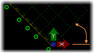
| Grid Preview | Used to preview the grid line graphics. Displays the selected grid system, including grid lines, grid bubbles and labels. Selected grid lines are displayed in red. Deselected grid lines are displayed in green. |
| OK | Used to save all changes. Closes the dialog. |
| Cancel | Used to delete all changes. Opens a warning dialog: "Changes to the Grid Systems(s) have not been saved. Do you want to save before proceeding?" |
| Create/Update Grid Models | Used to create and update the DGN models containing
the grid systems. A DGN model is created for each floor. On it, the grids defined for that floor are
included.Also saves the changes made to the grid systems.
Note: When grid
system models are created, the file specified by the
configuration variable
MS_DESIGNMODELSEED
is used as the seed file. The model specified by
configuration variable
MS_DESIGNMODELSEEDNAME
is used as the seed model. If these configurations can
not be resolved (do not exist), the active model is used as the seed model for
the grid system models. If the
MS_DESIGNMODELSEED
/MS_DESIGNMODELSEEDNAME
configured design seed model is used (not the active
model) the contents of the seed model are copied. This includes existing
elements, ACS definitions, reference attachments, etc.
|