| Add Building
|
Creates a top level container for storing floor and
reference plane definitions. With focus in the text field, the name for the new
building is entered to replace the default name. Buildings are listed in the
order they are created in the tree view.
|
| Add Floor
|
Creates a new floor entry at the next higher
elevation in the current building. The floor entry appears in the bottom of the
Floor Manager list box. The new floor list box entry is an actively selected
text field which displays the default name
Floor1. With focus in the text field, the
name for the new floor is entered to replace the default name. A valid
elevation must also be entered before focus is returned to you.
|
| Insert Floor
|
Enabled for a selected floor in the Floor Manager
list box. Inserts a new floor entry in the current building above the current
floor. The floor name is labelled in incremental number and inherit the default
elevations and rotation values.
|
| Add Typical Floor
|
Opens the Create Typical Floor Group dialog where
floor groups are created. Several settings are completed in this dialog to
create a floor group.
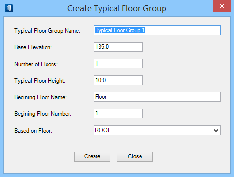
- Typical
Floor Group Name – Sets the floor group name to which a set of
typical floors belong.
- Base
Elevation – Sets the base elevation from which all typical floors
in the floor group are built.
- Number of
Floors – Sets the number of typical floors in the floor group.
- Typical
Floor Height – Sets the floor height of a typical floor which is
used to calculate the elevations of the typical floors in the floor group.
- Beginning
Floor Name – Sets the floor name, portions of which are used to
establish floor names for the typical floors in the floor group.
- Beginning
Floor Number – Sets the number of the lowest floor which is used to
establish the floor numbers for the typical floors in the floor group.
- Based on
Floor – Sets the floor definition from which all typical floors in
the floor group are built. All selected floor information and associated
reference planes are included. The option menu contains all current existing
floors.
- Create -
Creates the typical floor group.
- Close - Closes
the dialog. Does not create a typical floor group.
|
| Add Reference Plane
|
Creates a new reference plane associated with the
active and currently selected floor. The new reference plane list box entry is
an actively selected text field which displays the default name Reference Plane
1. With focus in the text field, the name for the new reference plane is
entered to replace the default name. A valid elevation must also be entered
before focus is returned to you. Reference planes are relative to the floor
with which they are associated and so are their elevations.
|
| Remove
|
Deletes the selected floor, floor reference plane, or
typical floor. Reference planes established within deleted floors are also
deleted. Typical floors associated with deleted master typical floors are also
deleted during this type of operation. Generally when typical floors are
deleted, elevations for typical floors above the deleted floor are lowered to
maintain a constant elevation between the remaining typical floors. You are
also given the option to maintain previous elevation(s) for the floors above
the deleted floor.
|
 (Relocate Building) (Relocate Building)
|
Enabled when you are working in the Floor Master DGN
(BB_FloorMaster.dgnlib). Moves the stack of floors and
reference plane shapes to a new location. To do so, identify and move a single
shape in a building and all the shapes in that building move on the XY plane.
|
| Settings
|
Opens the
Elevation
Annotation Settings dialog that defines properties of annotation in
elevation drawing views.
Note: These settings
get reflected in the drawing models created in the Dynamic View mode.
Tip: If
Elevation Line Margin is set to any
negative value (the precise value is unimportant), floor elevation lines in an
Elevation dynamic view are drawn with no gaps; they extend all the way through
the range of the dynamic view reference.
|
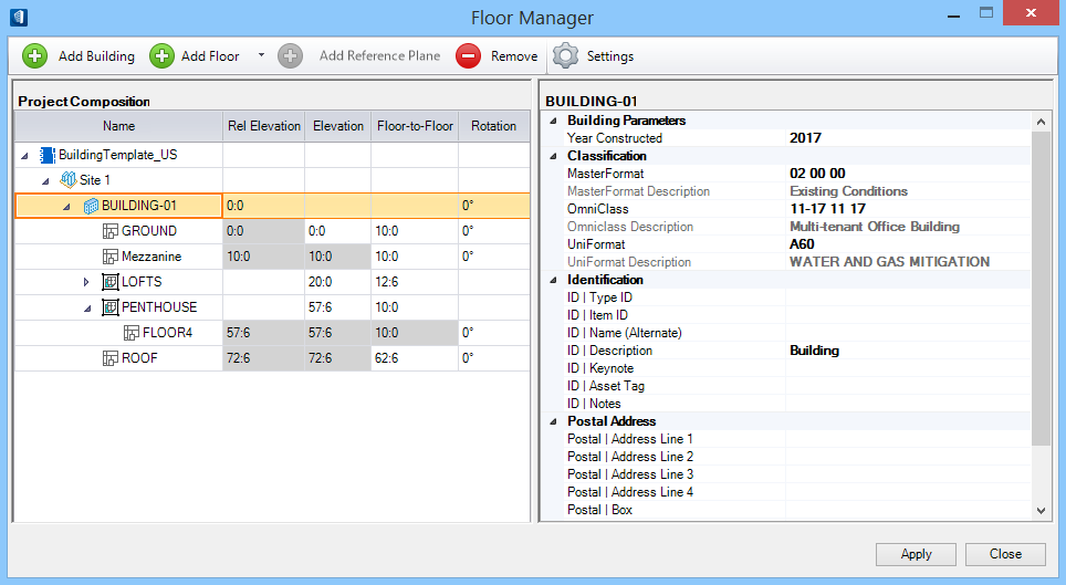
| Project Composition
|
The Floor Manager tree view list displays floors,
reference planes, and typical floor groups for the active project. Properties
and property values for selected floor definitions display in the Floor Manager
Properties list box. Floors, floor reference planes, and typical floor groups
displayed in this list box are sorted by ascending elevations, low to high.
Duplicate name occurrences are permitted as multiple floors can have the same
name. The following columns of list box information are available.
- Name - Displays
the names of floors, floor reference planes, typical floors and typical floor
groups. Floors and their elevation values are sorted in ascending order.
- Rel
Elevation - Displays the elevation for each item listed relative to
the value entered in the
Rel Elevation field (which is relative
to the real world elevation). The relative elevation values for floors,
reference planes and typical floors are calculated using the floor
Elevation and the
Floor-to-Floor values.
Rel Elevation values for all floors are
non-editable except the ones for building definitions. Building Rel Elevation
fields are editable by double clicking in the cell. Editing adjusts the values
in
Rel Elevation cells for all floors and
reference planes in the building.
Note: Generally,
relative elevations can be used to compensate for differences in elevation such
as topographic elevation between building floors or between buildings in a
project. The following examples are offered to clarify this.
- A building is
located at 325 topographic feet above sea level. In projects created by an
architectural discipline, the real world elevation would be 325 feet but the
relative elevation of the ground floor would be 0 feet. In this instance, the
Rel Elevation expresses a
difference in elevation that is relative to topography.
- Floor
reference planes are owned by the floor that defines them. Because of this,
Elevation does not change for
reference planes regardless of discipline. To make this point using the example
above, assume that ceiling height for all building floors is 10 feet. When
considering the ceiling reference plane,
Elevation for the 15th floor, it
is easier to work with a value of 10 feet versus 560 feet. In this instance,
the relative elevation of the ceiling reference plane is relative to the floor
that defines the plane.
- Elevation -
Displays the elevation for each floor, floor reference plane and typical floor.
Only "Floor-1" elevations can be set and the rest of floors follow the
elevation change.
- Floor-to-Floor
- Sets the floor to floor height for each floor, floor reference plane and
floors in typical floor group. Resetting floor-to-floor value for a floor
(except that of typical floors) alters elevations in successive floors.
- Rotation -
Rotates the active coordinate system for the selected floor on the horizontal
plane. The rotation displays most notably in the plan view by a rotated grid.
The rotation angle is zero degrees by default. Unless the user changes the
settings, sub floors and reference planes share the same angle as the base
floor.
Tip: Floor rotations, defined in the
Floor Manager, use the angle accuracy defined in the active file which can be
set in the
Design File Settings Dialog (key In:
MDL LOAD DGNSET). This
is done by selecting the
Angle Readout category of settings,
and using the
Accuracy menu to set the accuracy
setting.
|
| Properties
|
The Properties list box displays the attributes
assigned to the selected
Project Composition entry. Datagroup catalog
properties and values display here in two columns. The value column displays
property values by row. Information in the value column can be modified by
selecting the applicable row cell to activate an option menu or an editor
field.
- Building
Parameters - Visible for Building
Project Composition entries. Used to
enter the year of construction for the selected building.
- Classification
- Visible for Building, Floor, Typical Floor and Reference Plane
Project Composition entries. Sets
Building Classification properties. MasterFormat,
OmniClass, and UniFormat property values can be associated with the selected
entry. The Classification System selection menu is populated with
Classification property values.
- Discipline -
Visible for Floor, Typical Floor and Reference Plane Project Composition
entries. Sets the Building application discipline. Available discipline options
are: Architecture, Structural, Mechanical, and Electrical.
Note: Analysis
applications like RAM Structural System requires that structural members be
assigned to specific floors in a structure. Therefore, the
Discipline property for each floor
must be set to "Structural" to export floors to RAM Structural System. Floors
imported from RAM Structural System automatically set the Discipline property
to Structural.
- Floor - Visible
for Floor, Typical Floor and Reference Plane
Project Composition entries. Contains
these properties:
-
Gross Area - Sets the gross area
value for the floor, reference plane, and typical floor. Gross area is the
total area that a floor can have, including walls and all construction
elements.
-
Raw Area - Sets the raw area value
for the floor, reference plane, and typical floor. Raw area is the actual area
inside a room perimeter, not including walls and construction elements.
-
Net Area - Sets the net area value
for the floor, reference plane, and typical floor. Net area is the gross area
minus area generally not usable by occupants - area taken by elements such as a
columns and walls.
-
Occupancy Type - Sets the occupancy
type for the floor, reference plane, and typical floor.
-
Owner - Sets owner/creator
information for the floor, reference plane, and typical floor.
-
Remarks - Sets applicable remark
information regarding the floor, reference plane, and typical floor.
- Floor
Parameters - Visible for Floor, Typical Floor and Reference Plane
Project Composition entries. Contains
these properties:
-
Description - Sets the description
of the floor, reference plane, and typical floor. The default entry is no
description.
-
Length (Approx.) - Sets the
approximate distance of the floor shape edge along the X axis. Default values
are 200 feet (Imperial) and 100 meters (Metric).
-
Width (Approx.) - Sets the
approximate distance of the floor shape edge along the Y axis. Default values
are 120 feet (Imperial) and 60 meters (Metric).
-
Annotate - Sets the annotation to
apply or not (True or False).
Note: Approximate length and width
settings are used to create the floor range and clipping volume used by the
Floor Selector tool. You can modify the floor shape to create an exact
representation of a floor footprint.
- Identification
- Visible for Template, Site and Building
Project Composition entries. Used to
enter information such as general description, an alternate name or notes.
- Postal
Address - Visible for Site and Building
Project Composition entries. Used to
enter address, postal code, city, state and country information.
- Structural Floor
Parameters - Visible for Floor, Typical Floor and Reference Plane
Project Composition entries. Contains
these properties:
-
Column Splice Floor - This is an additional component of
floor/story definitions required for exchanging data with RAM Structural
System. Each floor definition contains an attribute that may be set to True or
False dictating whether the floor is to be recognized as a splice level. The
attribute corresponds to the state of the Splice Level setting in RAM
Structural System.
|
| Right-click options
|
Based on the current floor element selected in the
project composition tree, one or more of below right-click menu options are
available:
-
Add Building - Adds new building in the
tree view. This options is available for all floor elements in the tree.
-
Add Floor - Creates a new floor that is
next higher floor in the current building. This options is available when a
building or any floor element is selected.
-
Insert Floor - Inserts a new floor just
above currently selected floor.
-
Add Typical Floors - Adds a typical
floor group via the Create Typical Floor Group dialog where by default next
higher floor is taken for based on floor settings.
-
Add Reference Plane - Creates a new
reference plane associated with the active and currently selected floor.
-
Remove - Removes currently highlighted
floor element, except site from the Floor Manager list box.
|
| Apply
|
Applies changes made in the dialog. The recent
changes in bold text will temporarily change to normal, and disable the button
until more changes are made.
|
 Used to create and manage
floor definitions, floor and sub-floor reference planes and floor groups, and
floor information for projects in a Master Floor File
(BB_FloorMaster.dgnlib). The Floor Manager dialog is also
used to insert floors, modify and delete floors and associated reference planes
and floor groups as well as set elevation annotation.
Used to create and manage
floor definitions, floor and sub-floor reference planes and floor groups, and
floor information for projects in a Master Floor File
(BB_FloorMaster.dgnlib). The Floor Manager dialog is also
used to insert floors, modify and delete floors and associated reference planes
and floor groups as well as set elevation annotation.