Create an Overall Building Space
Conceptual Design involves defining the concept building's overall shape using MicroStation solid modeling tools. This is referred to as a mass model. Conceptual Design uses a special Trace space tool to create a single space (Room) to fill the mass model by tracing the shape of the building. The Trace space tool is similar to Trace Room in that it is used to draw a shape to define a space, but does not have the room creation options as for Trace Room.
-
Click
 (Place Slab), and
enter three data point for the slab form length, width and height.
The slab solid is created creating the
rectangular part of the building.
(Place Slab), and
enter three data point for the slab form length, width and height.
The slab solid is created creating the
rectangular part of the building.
-
Click
 (Place Cylinder), and
create a cylinder at one end of the slab solid.
(Place Cylinder), and
create a cylinder at one end of the slab solid.
- Keep the default Place Slab tool settings, and snap to the midpoint of the shorter side of the slab form at its base. Enter a data point.
- Snap to one of the corners on the same edge, and enter a data point. The AccuDraw Compass rotates to align with the z axis allowing you to define the cylinder form height.
- Press <Enter> key to lock the AccuDraw Compass in the Z direction
- Snap to the top edge of the slab form, and enter a data point.
-
Click
 (Unite Solid). Select
both forms, and Reset.
The 2 forms are united into one form.
(Unite Solid). Select
both forms, and Reset.
The 2 forms are united into one form.
-
Click
 (Trace Room).
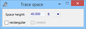
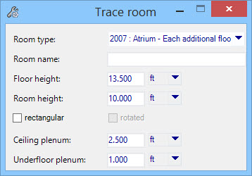
Activates the Trace space . Trace space is similar to Trace Room in that it is used to draw a shape to define a space, but does not have the room creation options as for Trace Room.
-
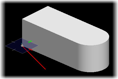
Keep the Trace space default tool settings, and follow the prompt
Trace space > Enter point (on the Status bar prompt area).
Snap to the corner of the mass model coincident with the origin marker (coordinate 0,0,0 in the AccuDraw window), and enter a data point. This establishes the first point on the floor plan.
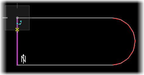
- Continue tracing the building floor plan. Snap to the edges of the mass model, and add data points.
-
After defining the last point on the floor shape, right click to
Reset out of the Trace Space mode.
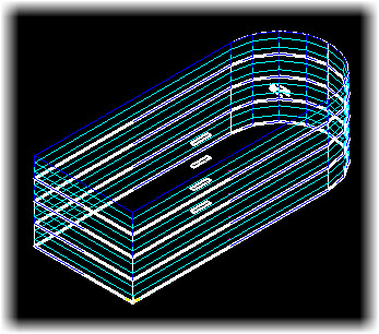
A 3D space is modeled with the traced space as its perimeter, and is divided into floors per the Floor Data settings.