|
|
Loads saved symbols from one of the settings files:
Weld 1 through Weld 5.
|
|
|
Saves the current symbol as Weld 1, 2, 3, 4, or 5.
|
|
|
Resets all settings to the default None.
|
|
|
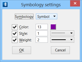
Activates the Symbology settings dialog.
You can use this dialog to change the color, style, and
weight for the listed symbol components.
Tip:
Apply by clicking OK.
|
| Standard
|
Choose the required standard from the drop list:
Tip:
Available welds and the symbol layout change to accommodate each loaded
standard.
|
| Direction
|
Select the direction from which the symbol will
move from the leader line. Values are:
- Auto — The symbol
will start or end at the leader line, depending on the direction of the leader.
- Right — The symbol
will be to the right of the leader line, regardless of the direction of the
leader.
- Left — The symbol
will be to the left of the leader line, regardless of the direction of the
leader.
|
| Association
|
Turn on this check box to create associations to
the elements.
|
| dialog symbols
|
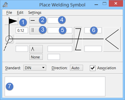
The dialog provides two sets of symbol and dimension data fields on
either side of the reference line. The essential symbols are activated by
feeding dimension data or included from the list.
- Weld size — field
no. (1)
- Contour symbol —
field no. (2)
- Weld symbol — field
no. (3)
- Finish, Groove
Angle, and Root Opening — field no. (4)
- Length, Pitch, and
Number of welds — field no. (5)
- Size of groove,
Effective throat — field no. (6)
- Tail –
specification, process reference — field no. (7)
|
| Welding Symbols
|
The skeleton of the welding symbol essentially
includes major graphical elements.
- Reference line — A
default horizontal reference line forms an essential part of welding symbol. It
acts as an anchor to which all the other welding symbols are tied.
- Side — The dotted
lines are required by one or more standards to define welds located on the
opposite side from where the arrow is pointing. Clicking just below or above
the reference line adds the side of the weld at arrow side or other side
respectively.
- Field weld — Shows
the flag towards the tail field weld, when activated indicates the welds are to
be made on the site, or at the place of initial construction. To exclude the
field in the welding symbology, click another time to deactivate.
- Weld-all-around
symbol — Places a circle at the field weld flag indicating a continuous weld
which may:
- Extend
completely around a joint.
- Extend
completely around a joint which includes more than one type of weld, indicated
by a combination weld symbol.
- Extend
completely around a joint in which the metal intersections at the points of
welding are in more than one plane.
- Staggered
Intermittent weld — Appears for the ISO and DIN standards.
- Tail — When
activated, supplementary information about the welds in the welding symbol are
keyed in the field at the bottom of the extended dialog.
- Specification,
process, or other reference (field no. 7) — The weld process ident stores the
reference to the welding process, the electrode, a detail drawing, or any
information that aids in the making of the weld that does not have its own
special place on the symbol. For example, A definite process reference, such as
CP indicates complete joint preparation, E7018 indicates preferred type
electrode.
Note: Other than
reference line the rest of the graphical elements add supplementary indicators
to welding symbol.
|
| Weld symbol options
|
The dialog provides two sets of symbol options on
either side of the reference line; one for choosing the weld, and another for
the contour symbols (by default they all are set to None).
Click on the option menu to choose the graphic of
appropriate to weld symbol.
- Contour symbol
option (field no. 2) — Use the menu options list to choose one of the contour
symbols from the list.
- Basic weld symbol
option (field no. 3) — Use the menu options list to choose one of the contour
symbols from the list.
Note: The list
varies depending on the current standard applied.
|
| Weld dimensions and other data
|
The rest of the fields, four on each side, accept
alphanumeric data to be added in the welding symbol.
- Weld size (field
no. 1) — Specifies the weld sizes. For fillet welds, numbers to the left of the
symbol indicate the design throat thickness, leg length, or both design throat
thickness and leg length requirements.
The weld sizes could be specified with standard
designations, say for ISO standard a7 z 10, a7 b 10 etc.
where;
- Finish / Groove
Angle / Root Opening (field no. 2) — Sets the Finish, Groove Angle, or Root
Opening value as applicable for the weld being defined.
- Length, Pitch, and
Number of welds (field no. 5) — The intermittency field sets the length, and
pitch or number of welds.
For example,
Keying values 3 – 6 for length and pitch
imply 3 weld deposit and 6 as the centre to centre spacing of each stitch. [L
– P]
The number of welds is wrapped in bracket next
to the length when the dimension is specified without quoting the pitch. [L
(N)]
- Size of groove,
Effective throat (field no. 6) — This field supplies dimension applied to the
groove weld, interpreted internally for the right symbol.
For example,
½ (¾) — takes depth of groove and effective
throat in parentheses.
|
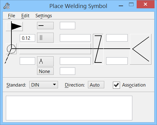
 Used to place a welding
symbol in an extracted drawing or model. Accessed from:
Used to place a welding
symbol in an extracted drawing or model. Accessed from: