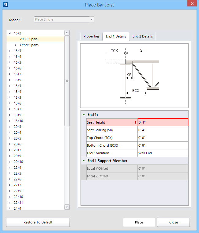
Contains settings that specify details about the first end
of the bar joist you are modeling. Enter values for seat height, seat bearing
and chord extensions. A schematic diagram of a bar joist end configuration is
provided as a reference.
| Setting | Description |
|---|
| End 1:
|
Contains settings that determine the configuration
at the bar joist's first bearing end.
- Seat
Height — Determines the vertical offset distance between the
bearing seat member to the top edge or surface of the top chord.
- Seat
Bearing (SB) — Determines the length of the seat bearing member
which rests on the support member/element.
-
Top Chord (TXC) — Determines the
distance the top chord extends beyond the seat bearing point (labeled "TCX" in
the diagram).
- Bottom
Chord (BXC) — Determines the distance the bottom chord extends
inside the seat bearing point (labeled "BCX" in the diagram). Although
editable, the BCX value is initially determined by the SJI standards data for
the selected series code.
- End
Condition - Sets how the end of the joist is constructed.
-
Steel End — Select this option if
this end will be modeled on a steel end.
- Wall
End — Select this option if this end will be modeled on a wall end.
Note: The SJI (Steel
Joist Institute) publishes standards for bar joists. One portion of the
standards describes minimum seat heights. The Bar Joist Modeling tool
automatically performs a SJI code check based on the standards. If seat heights
do not respect the guidelines, yellow warning icons are displayed next to the
Place button and at the bottom of the dialog.
|
| End 1 Support Member
|
Contains information and settings related to the
support member at end 1. These settings are only enabled when the bar joist is
associated to a Structural member. Member association occurs when the bar joist
is placed using the place multiple mode.
- Local Y
Offset — Displays the local Y-axis offset of the end 1 support
member.
-
Local Z Offset — Displays the local
Z-axis offset of the end 1 support member.
-
New — Enabled for the
Modify Joist Mode. Click to select a new
end 1 support member. The new member's section and local offset information is
automatically updated.
-
Flash — Enabled for the
Modify Joist Mode. Click to momentarily
change the display of the support member. Used when the supporting member is
visually difficult to identify.
|