Place Bar Joist
 Used to automate bar joist
modeling by utilizing data from SJI (Steel Joist Institute) standards. Place,
modify, or manipulate bar joists by establishing a span and selecting a bar
joist series.
Used to automate bar joist
modeling by utilizing data from SJI (Steel Joist Institute) standards. Place,
modify, or manipulate bar joists by establishing a span and selecting a bar
joist series.
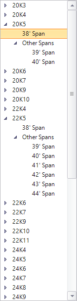
The Place Bar Joist tool supports K, LH, DLH and SLH series bar joists. K series are used in common applications typically spanning 8 feet (2.5 m) to 60 feet (18.3 m) with depths between 8 inches (203 mm) to 30 inches (762 mm). LH, DLH and SLH span progressively larger distances with progressively larger depths.
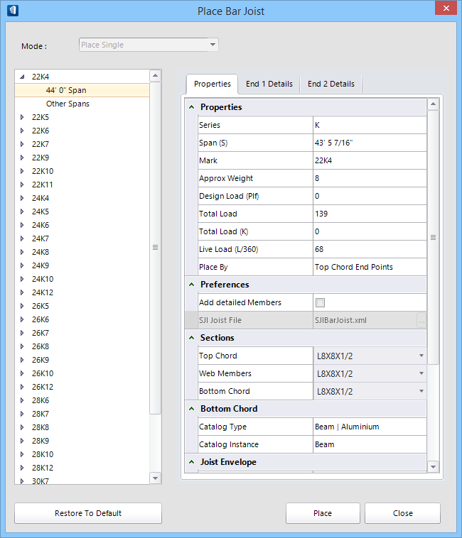
Bar Joist Modeling dialog
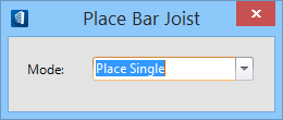
Initially, selecting
opens a preliminary dialog
which governs the main tool settings window.
| Setting | Description |
|---|---|
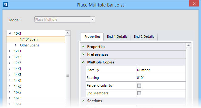
| Mode | Select the placement or modification modes used for designing bar joists. Selections made here determine the prompts that guide you through the tool modes. |
| Place Single | One bar joist assembly is placed as a compound cell along the selected span. Spans are specified using data points between structural members or other elements. |
| Place Multiple | Multiple placement requires the selection of two members establishing a span. Additional settings related to multiples appear in the Properties tab. |
| Modify Joist | Previously placed bar joists are modified by selecting this option and then selecting the bar joist. Modify seat heights, series and section definitions for example. |
| Manipulate Joist | Previously placed bar joist spans are manipulated using this option. Drag the element representing the span to change its length or direction. Once a new end point is selected, the Bar Joist Placement Program dialog reappears where modifications are made to the various settings like series, loads and sections. |
Construction elements
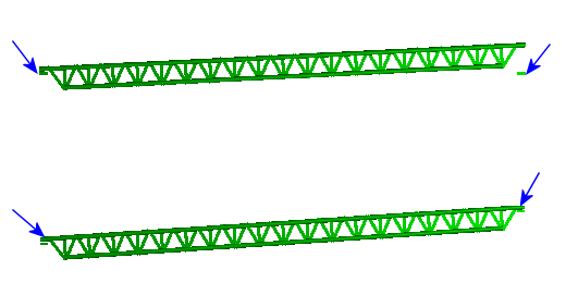
Temporary construction elements appear during placement and manipulation providing assistance with visualizing bar joist seat height and span attributes.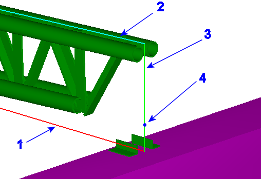
- Bearing Line — Represented by a red line, the bearing line is the line drawn when defining a span in both single and multiple placement modes.
- Span — Represented by a cyan line, the span is the actual bar joist span. It is always displayed along the top chord.
- Seat Height — Represented with a green line, the seat height is the offset distance from the bearing member to the top chord. Seat height is defined on the end detail tabs.
- SJI Minimum Seat Height — Represented with a blue dot, the SJI (Steel Joist Institute) minimum seat height is derived from the SJI data associated with the specific bar joist configuration chosen.
SJI Code Check
The SJI (Steel Joist Institute) publishes standards for bar joists. One portion of the standards describes minimum seat heights. Seat height minimums depend on:
- Joist series (K, LH, DLH and SLH)
- Joist slope.
- Top chord depth.
- Width of support member (when associated during multiple placement)
- Top chord extension
- Chord section definitions
| Setting | Description |
|---|---|
| SJI code check messages | If the seat heights are outside the guidelines (Standard Specifications, 42nd Edition, Load Tables and Weigh Tables for Steel Joists and Joist Girders, pages 10-11), the Seat Height parameter is displayed in red, and a flyover hint is displayed showing the recommended SJI seat height. Warnings are also displayed (in the Message Center) when attributes such as the top chord extension, the top chord section depth, the support members and the joist series, all of which influence the minimum seat heights, are modified. |