OpenBridge Modeler

Place Bearing tool

Used to place bearings under beams or deck on existing pier lines.

Found on the Home ribbon tab in the Substructure group.

Tool Settings

SettingDescription
Bearing group
SettingDescription
Bearing Type Select the type of bearing to use:
  • Cube — Type the Cube Length, Cube Width, and Cube Height
  • Cylinder — Type the Cylinder Radius and Cylinder Height
  • Cell — Select a library object from BearingLib.cel (a MicroStation cell library file).

    Click the […] button adjacent to the Cell field to select an object. Specify the Active Angle and X- / Y- / Z- Scale values.

Orientation Indicates whether the bearing is oriented parallel to the Pier or parallel to the Girder.
Placement group (for bearings under box girders only)
SettingDescription
Back Offset Back station offset value.
Ahead Offset Ahead station offset value.
Transverse Offsets Type a offset transverse to the alignment. Use a semi-colon separated list to generate multiple bearings in a line under box beams or slabs.
Grout Pad group
SettingDescription
Has Grout Pads Set this option if grout pads are present. Specify additional grout pad parameters.
Pad Thickness Definition Chose to input this thickness for center of pad or as minimum thickness.
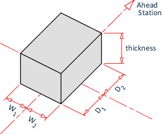
Pad Thickness / D1 / D2 / W1 / W2 Dimensions of the rectangular prism grout pad. Plan dimensions are measured from the longitudinal (ahead and back station) and lateral offset center.
Pad Orientation Indicates whether the grout pad is oriented parallel to the Pier or parallel to the Girder.
Bearing Seat group
SettingDescription
Has Bearing Seats Set this option if bearing seats are present. Specify additional bearing seat parameters.
Model Stepped Cap (for bearings under beams only) Use a stepped cap for bearing seat elevations varying across the superelevation along the supportline.
Seat Min. Thickness / D1 / D2 / W1 / W2 Dimensions of the rectangular prism bearing seat. Plan dimensions are measured from the longitudinal (ahead and back station) and lateral offset center.

Beam Seat Dimension Detail and Orientations

  • Width (W1) - Dimension to the left of the bearing center when looking toward the opposite end of the girder.
  • Width (W2) - Dimension tot he right of the bearing center when looking toward the opposite end of the girder.
  • Depth (D1) - Dimension forward of the bearing when looking toward the opposite end of the girder.
  • Depth (D2) - Dimension rear of the bearing when looking toward the opposite end of the girder.
Seat Orientation Indicates whether the bearing seat is oriented parallel to the Pier or parallel to the Girder.
Path group
SettingDescription
Back Offset Back station offset value.
Ahead Offset Ahead station offset value.
First Offset (Segmental only) Lateral offset for first line of bearings.
Second Offset (Segmental only) Lateral offset for second line of bearings.
Material group Select the material to use for object components by selecting the associated […] button and then selecting the material from the Material Library dialog.
Build Order group Assign a build order (ordinal integer) to each object component in this group to specify construction order.
Feature group
SettingDescription
Feature Definition Select an existing feature definition from the drop-down list to use for object being placed.
Name Prefix Type a prefix value to use for all objects set using this Feature Definition, which are useful in quickly identifying features in a group.
Key-in: bmgeom bearing < placeunderbeams | placeunderdeck >