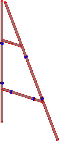
OpenBridge Modeler

Vertical A Frame

Used to parametrically create a vertical A frame structure, which are most commonly used in electrical substations but can be used for many other purposes.

Accessed from:
  • Ribbon: Steel > Home > Steel Connections > Substation Gallery
  • ... [Substation Structural Objects] > Vertical A Frame

Frame tab

Used to specify the overall frame geometry, the shapes used for the legs, and define the splice levels.

SettingDescription
Shape Class Selects the shape class to use for the members from the drop down list.
Shape Size Selects the shape size to use for the members from the drop down list.
Add Shape Size Opens the Add Shape Size dialog, which is used to define a new pipe shape.
  • Diameter - Sets the new pipe shape diameter.
  • Thickness - Sets the new pipe shape wall thickness.
  • Shape Size - Displays the corresponding custom pipe database entry closest to the Diameter and Thickness parameters you define.
  • Material - Selects the material for the new pipe shape.
  • OK - Closes the dialog and saves your changes.
  • Cancel - Closes the dialog without saving your changes.
  • Help - Opens online help.
Frame Size
  • Height - Sets the height of the A frame. Denoted with 1 in the diagram.
  • Top Width - Sets the width of the A frame at the top. Denoted with 2 in the diagram.
  • Bottom Width - Sets the width of the A frame at the bottom. Denoted with 3 in the diagram.
Split Point From Bottom The table is used to specify the location of split points (i.e., leg splices) along the height of the frame.
  • Table columns:
    • Level - Displays the level numbers.
    • Segment Length - Sets the length of the splice defining the split point along the height of the frame.
    • Elevation - Sets the elevation of the split point along the height of the frame.
    • Flange - Selects a flange component which is used to connect the splices.
  • Add - Adds a new row to the table.
  • Delete - Removes the currently selected row from the table.
  • Split by Segment Length - Chooses the method of the split. Use this option to specify splice levels along the length of the member. Enables the Segment Length column in the table.
  • Split by Elevation - Chooses the method of the split. Use this option to specify splice levels by elevation. Enables the Segment Length column in the table.
Plate Cut Bottom End When on, the bottom leg is cut horizontal relative to the ground. When off, the bottom leg is left normal to the leg orientation.
Rotate Rotates the Substation Gallery object by the angle entered in the available value field. Click Rotate to complete the rotation.
Rotate by Point Rotates the Substation Gallery object by selecting a point in the model. Click Rotate by Point to complete the rotation.

Brace tab

Used to specify location, section, and splice data for horizontal brace members.

SettingDescription
Brace members table Specifies the Elevation, ShapeClass, ShapeSize, number of splits (i.e., splices), and location of splices for each level of the brace.

Table columns:

  • Level - Lists the number of horizontal bracing levels in the A frame.
  • Elevation - Sets the vertical location or height of the brace levels. Denoted with 5 in the diagram.
  • ShapeClass - Selects the shape class to use for the brace members at each level.
  • ShapeSize - Selects the shape size to use for the brace members at each level.
  • SplitCount - Sets the number of splits (splices) in the brace members.
  • ToCenter - Sets the distance between the splits and the center of the trestle structure. Denoted with 6 in the diagram.
  • Flange - Selects a flange to fasten the brace members where they are spliced.
Add Adds a bracing level to the table.
Delete Removes the currently selected row from the table.
Add Shape Size Opens the Add Shape Size dialog, which is used to define a new pipe shape.
  • Diameter - Sets the new pipe shape diameter.
  • Thickness - Sets the new pipe shape wall thickness.
  • Shape Size - Displays the corresponding custom pipe database entry closest to the Diameter and Thickness parameters you define.
  • Material - Selects the material for the new pipe shape.
  • OK - Closes the dialog and saves your changes.
  • Cancel - Closes the dialog without saving your changes.
  • Help - Opens online help.
Boolean Cut With Leg When on, you can specify a boolean cut of the brace member end to conform to the supporting leg member shape.
Gap Sets a gap cut at the ends of the brace members. Denoted with 7 in the diagram.

Group tab

Used to create a new OpenBridge Modeler group with the Substation Gallery objects.

SettingDescription
Create Group Select this option to select additional shapes. Separate Substation Gallery objects are created.
Group with Bolts/Welds Select this option to group bolts and welds.
WorkFrame
  • Create View - When on, work frame views are created.
  • Prefix - Used to enter a prefix for the work frame views.
  • Front/Rear Clip Distance - Sets the clipping distance for the work frame views.

Assignment tab

Used to assign elements in the connection to a material, display class, area class, part family, level, etc.

Dialog Controls

SettingDescription
OK Closes the dialog and save your changes.
Cancel Closes the dialog without saving changes.
Help Opens online help.
Template Saves and retrieve (Using Templates) settings to be used on other projects.
Clone Shifts focus to the geometry, allowing cloning the current structural object (stair, frame, truss, etc.) properties to match one or more objects selected in the view.
Show /Hide Preview Opens or closes, respectively, a flyout panel to display an illustration based on the tool.
Key-in: PROSTEEL CREATE VERTICALAFRAME