Simple Structure
 Used to parametrically create a
simple structure (frame).
Used to parametrically create a
simple structure (frame).
Though simple structures are most commonly used in electrical substations, this tool can also be used for many other purposes.
Accessed from: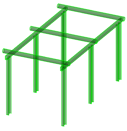

Column tab
Used to specify geometry, section sizes, and orientation of simple structure columns.


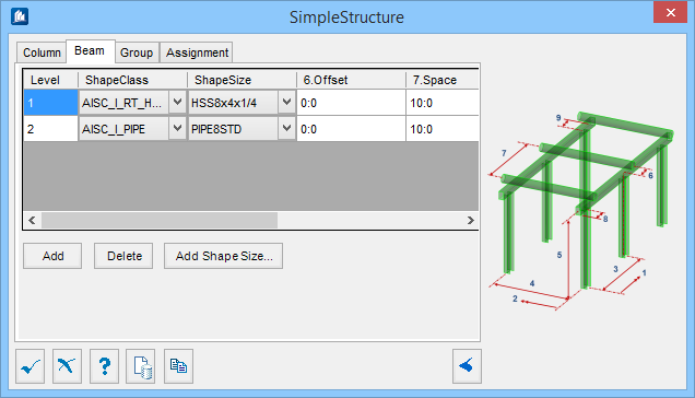
Beam tab
Used to specify shapes and spacing of the longitudinal and transverse beams in the simple structure.
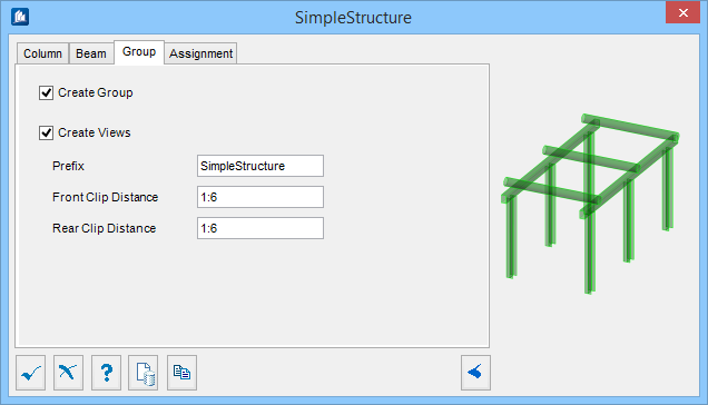
Group tab
Used to create a new OpenBridge Modeler group with the Substation Gallery objects.
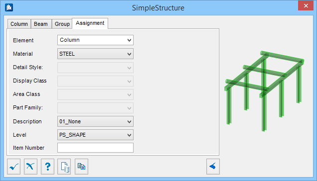
Assignment tab
Used to assign elements in the connection to a material, display class, area class, part family, level, etc.
Dialog Controls
| Setting | Description |
|---|---|
 OK OK
|
Closes the dialog and save your changes. |
 Cancel Cancel
|
Closes the dialog without saving changes. |
 Help Help
|
Opens online help. |
 Template Template
|
Saves and retrieve (Using Templates) settings to be used on other projects. |
 Clone Clone
|
Shifts focus to the geometry, allowing cloning the current structural object (stair, frame, truss, etc.) properties to match one or more objects selected in the view. |
  Show /Hide
Preview Show /Hide
Preview
|
Opens or closes, respectively, a flyout panel to display an illustration based on the tool. |