User Part Data dialog
Used to enter data for individual blocks for the database fields created in the User Defined Data Fields dialog.
Accessed from:
| Setting | Description |
|---|---|
| Folder | Displays the location of the currently selected user part. |
| User Part File | Displays the file name containing the currently selected user part. |
 OK
OK
 Help
Help
 Add
Add
Pre-defined Data fields
To facilitate the acquisition of standard data, certain pre-defined data fields (standard fields) are created upon creation of parts, the contents of which can be automatically taken from the model. These data fields are managed in the same way like any standard user-defined data fields and therefore can be modified or deleted, too.
If one or more of these data fields are deleted, they are not taken into consideration any more at database update or upon creation of parts. To restore these fields, it is necessary to re-structure the database or to create the field manually together with the exact name.Automatic Creation of Database
At first start of the program or at modification of part directory, it may be that there isn't yet any database existing. In this case, a blank database is always created to adopt parts.
The program offers you to search in the part directory including all sub-directories for drawings and to adopt them into the database. This allows you to manage even earlier created parts via User Part Center.When you give a negative answer to this query, only those parts are displayed which are to be created later with the help of the User Part Center – even if there are still other drawings in the directories. It is possible to create a complete new database at any time you like.
New Creation of Database
At any time, it is possible to replace the existing database with a new one without having to delete the database file. Just click on the entry Create new Data Records in the context menu of Navigation dialog. The application then searches in all subordinate directories for drawings to be adopted into the database.
Update of Database
Select in the Navigation dialog to update an existing database. In this scenario, the application searches for DGN files, which do not exist any more in the part directory, and removes them from the database. At the same time, new drawing files and sub-directories are adopted into the database.
At update of the database, the entered data and modifications of data fields are kept. You may define via pre-settings what has to be done with the standard fields during update.
When the option Don't replace standard fields is selected, no entries in the standard fields are modified, new drawings are not examined.
When the option Always replace standard fields is selected, all DGNs are searched for standard data and any possible modifications are lost.
When the option Only replace blank standard fields is selected, newly added drawings are examined, as their standard fields are still blank. All others are not taken into consideration.
When some standard fields are removed from the database, they are not restored during update. With database update, it is, however, possible to make sure that modifications in the part files cause an update of the remaining standard fields. The application assumes that deleted standard fields are required any more.
Display Filter
Another strength of the User Part Center is the display filter. Before the parts are displayed in the selected sorting, the application first checks whether each single part meets the filter conditions on the basis of its database entries.
For this purpose, logical links may be created between the existing data fields and their contents. There is no limit to the complexity of the query. Different filter combinations can be stored as templates and then defined as activated filter in the settings for the sorting.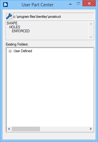
You may for instance, specify only parts having holes are displayed if they have 4 enforced holes.
Then, the neighboring figure shows you the result of filtering at a given sorting according to shape, hole pattern and if they are enforced.
To be able to work reasonably with the filters, you should have a certain mathematical understanding of logically linked notions. It is very easy to create a filter condition never producing any positive result at all in combination with the existing data – a corresponding check doesn't take place.
Boolean operators
Simple queries only consist of one comparing condition such as e.g. hole pattern = 4. It is, however, the logical link between several comparing conditions.
You may specify a logical operator by means of which the next inserted comparing condition shall be linked with the existing condition. To facilitate input, previous pairs are automatically put into brackets, in case of a change of the operator. It is possible to create search queries such as (A AND B) OR (A AND C) in an easy way. A, B and C here are variables of simple comparing conditions of data field, operator and content.
An existing term can be manually put into brackets, too, if the condition is not in pairs. The following condition serves as example: ((A AND B) OR C) AND D.