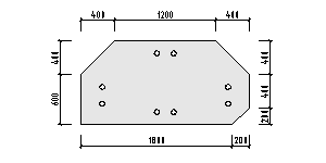
Dimensioning for parts, end plates, and anchor details
Contour dimensions
| Setting | Description |
|---|---|
| Cluster dimensions | Continuous dimensioning chains from the beginning to the end of the part respectively on the processing side. |
| Setting | Description |
|---|---|
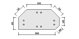
| Edges individually | Individual dimensions along each edge that is available in the part view. |
| Setting | Description |
|---|---|
| Edges merged | Individual dimensions along each diagonal edge. In addition, continuous dimensioning chains from the beginning to the end of the part. |

Hole dimensions
| Setting | Description |
|---|---|
| Cluster dimensions | Continuous dimensioning chains from the beginning to the end of the part each on the side of the holes. |

| Setting | Description |
|---|---|
| Hole groups | Continuous dimensioning chains in a horizontal direction from the beginning to the end of the part. Individual dimensioning chains per hole set in a vertical direction. |

| Setting | Description |
|---|---|
| Edge reference | Individual dimensioning chains per hole set, based respectively on the nearest part edge. |

For the anchor details there are various selection options for the cluster dimensions, each with different reference points.
| Setting | Description |
|---|---|
| Cluster dimensions Object reference | Continuous dimensioning chains from the beginning to the end of the anchor plate. |
| Cluster dimensions Column reference | The dimensioning chains begin at the middle axis of the corresponding struts without closed components. |
| Cluster dimensions Grid axis | The dimensioning chains begin at the nearest axis without closed components.. |
Additional dimensions
| Setting | Description |
|---|---|
| Reference | The distance between both component reference points in a horizontal direction. |

Total dimensions
| Setting | Description |
|---|---|
| Radian dimensions | The length of the arc, as well as the enclosed angle, in the longitudinal direction are given simultaneously. The length of the arc refers to the middle axis. |

| Setting | Description |
|---|---|
| Length, width, and radian dimensions | In addition to the radian dimensions, the orthogonal dimensions are also given. |
