Content of standard templates
The following compilation should explain the practical impact of the individual templates supplied, since this cannot currently be viewed directly on the assistant pages. A support graphic for this template group is all that appears on selection from a selection list.
Like all templates in OpenBridge Modeler, the templates are organized as a hierarchical structure whereby only the complete path appears in the selection list (and not the tree structure).
General information on the dimensioning templates
Here you will find a compilation of all possible selection sets for dimension chain settings, from which you can compose a complete dimensioning within the different component areas.
Since a description of each individually available template is beyond the scope of this manual, only the structure and some of the abbreviations used in the names will be described. Many of the terms here are self-explanatory.
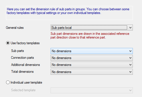
The example below shows the selection of two dimensioning templates for the creation of a dimensioning for sub parts in structural groups.
Selection sets of dimensioning templates
| Setting | Description |
|---|---|
| Contour dimensions | These are the modification dimensions of the outer contour (if necessary the inner contour) through sections, notching etc. for parts. |
| Hole dimensions | These are the holes in their top view (and in the side view too, if necessary) for parts. |
| Additional dimensions | Special dimensions like reference points, axis etc. |
| Total dimensions | The total dimensions of the component or model view. |
| Mounting dimensions | These are the mounting dimensions of profiles, poly plates, stiffeners etc. inside the structural groups. |
| Connection dimensions | These are the mounting dimensions of the end plates, brackets, purlin angles etc. within the structural groups. |
| Elevation dimensions | These are the mounting dimensions of profiles, which appear in the model view as a view of their flange or web. |
| Section dimensions | These are the mounting dimensions of profiles, which appear in the model view as a view of their cross-section. |
Structure of template names
Here you can see a typical example of the structure of a template name for the dimensioning of sub parts:
Straight / Only primary view/ Outer edges
| Setting | Description |
|---|---|
| Straight | Used dimensioning points |
| Only primary view | Restriction of the position (not always available) |
| Outer edges | Main orientation of the dimensioning |
Meaning of the main orientation
Most of the templates begin with Radial and Straight. This describes the main orientation of the dimensional chains. The meaning of these terms is as follows:
Meaning of the component position
| Setting | Description |
|---|---|
| Primary view | View of the web or flange of a profile and/or the surface of a slab (and flat-rolled steel). |
| Secondary view | View of the cross-section of a profile and/or the edges of slab (and flat-rolled steel). |
The pages below contain a list of the most important format types for the dimension points in the various selection sets and components and/or model views.