| Layout
|
Sets the shape of the inner corners of the
stiffeners, one from the available options:
- Use
Flat – A flat steel is used instead of a poly-plate. The flat is
processed by Boolean operations in a way as if its shape would be identical
with a poly-plate.
- Search
Closest Flat – The current polyplate is replaced by the closest
fitting flat steel. No user-specific flat steel is created.
|
| Length
|
Sets the length of the stiffeners, based inner edge
form selected from the drop-down list;
- Full
Stiffener – The stiffener height extends over the complete web
height of the shape.
- Half
Stiffener – The stiffener height stretches over half the web height
of the shape where the side is determined by the picked side.
- By
Length – The stiffener is given the height specified by you. Only
values between 10-90% of the web height can be used.
- Edge
– The height of the stiffener is determined according to the specifications,
but the layout is a triangle shape.
|
| Placement
|
Controls whether stiffeners are created on both sides
or one of the sides only.
Note: This selection will be ignored for shapes like 'C' which
allow one stiffener only.
- Both
Sides
– This is Default selection. Creates stiffeners on
both sides.
- Near Side
–When Near Side is selected and applied on shapes
that support two stiffeners, the stiffener is created only on one side. It will
be on front side for a beam created from left to right.
- Far Side
– When Far Side is selected and applied on shapes
that support two stiffeners, the stiffener is created only on one side. It will
be on rear side for a beam created from left to right.
Note: When Near or Far side options are selected then punch holes
are created only on one side of the beam, and that will be on the side where
stiffener is created.
|
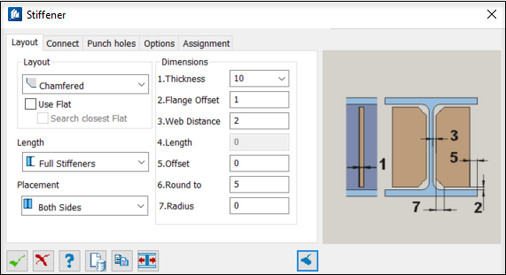
| Dimensions
|
- Thickness –
Sets the thickness of the stiffener plate; this value is taken from the table
or it can be entered freely if this setting has been activated.
- Flange
Offset – When calculating the stiffener dimensions, this is the
distance to the flange side, i.e., the stiffener height is slightly reduced.
- Web
Distance – When calculating the stiffener dimensions, this is the
distance to the web side, i.e., the stiffener width is slightly reduced.
- Length – This
is the value for the stiffener length when you have selected the stiffener
length ‘To Measure’.
- Offset – When
calculating the stiffener dimensions, this is the distance to the outer edge of
the flanges, i.e., the stiffener width is slightly reduced. If the stiffener is
to slightly project towards the outside, type a negative value.
- Round
to – The Round to value describes a rounding accuracy applicable to
the width of the calculated stiffened plate. Rounding is carried out after
calculation of the projection.
Using this setting, it is possible, e.g., to
permit only dimensions divisible by 5, so that flat steel bars can be used.
- Radius – In the
Radius input field you specify the radius of the ribbed plate at the shape
radii. If this value is 0, the shape radius is imported. If you have selected
the create ‘Insert at Slant’, the radius is bridged by a slanted edge.
|