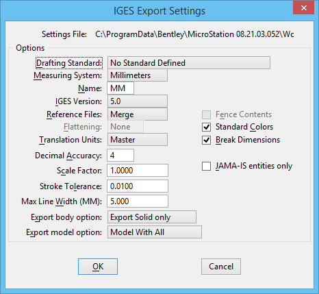
IGES Export Settings Dialog
| Setting | Description |
|---|---|
| Settings File | Displays the path and filename of the attached export settings file, which is defined by the configuration variable MS_IGESOUTSET. |
| Drafting Standard | Sets the drafting standard. |
| Measuring System | Sets the measuring system. |
| Name | Name of the measuring system in the IGES file. |
| IGES Version | Sets the IGES version (4.0 or 5.0) for the exported
IGES file.
IGES Version 4.0 does not support copious data entities (type 106) in composite curves. This makes it necessary to translate line strings in complex chains as multiple line entities (type 110). In IGES Version 5.0, this restriction is removed, allowing more compact translation of line strings in complex chains. This is the only difference between choosing IGES version 4.0 or version 5.0. |
| Reference Files | Sets how references are converted: |
| Flattening | Lets you translate a 3D DGN file to a 2D IGES file. Flattening is necessary if the receiving application does not support 3D. |
| Translation Units | Sets whether to equate IGES file units to either the
master units or sub-units of the active DGN
file.
For example, to export an architectural design with master units of feet and sub-units of inches to an IGES file with file units of inches, set Translation Units to Sub-Units. |
| Decimal Accuracy | Sets the accuracy, in decimal places, with which
coordinates from the DGN file are stored in the IGES file.
By default, Decimal Accuracy is set so that the maximum error is less than 1 positional unit. Changing this value is usually not necessary. |
| Scale Factor | Sets the scale factor that is applied to all
exported elements. This can be used to tailor the translation to create
geometry for receiving applications that read data at a different scale or in a
different coordinate system.
By default, set to 1.0 (no scaling). |
| Stroke Tolerance | The maximum deviation, in
Translation Units, between the actual
curve and the approximating line segments for arc, curve, B-spline curve, or
B-spline surface entities, if they are excluded.
If any of these IGES entities are excluded in the Exclude IGES Entities dialog (opened by choosing Settings menu/Exclude IGES Entities… in the Export IGES File dialog), they are approximated by line segments, referred to as strokes, in line string or shape elements. If stroke tolerance is decreased, the number of segments and the size of the exported IGES file is increased and the approximation quality is finer. If the stroke tolerance is increased, the number of segments and the size of the exported IGES file is reduced and the approximation quality is coarser. |
| Max. Line Width (MM) | Sets the IGES line thickness in millimeters (mm)
that is assigned to
MicroStation PowerDraft line weight 31. The
other line weights are assigned thicknesses that are proportional to this
value. For example, if Maximum Line Width is set to 5 mm (the default, about
0.2"), lines of weight 31 and 15 in the DGN file are 5.0 mm and 2.5 mm thick,
respectively, in the IGES file.
MicroStation PowerDraft line weights are not associated with a specific thickness, but instead determine the relative line weight of a line with respect to other line weight values. This lets line weight display be tailored to the display hardware. In contrast, line weights in IGES are specified by the actual line thickness. |
| Export body option | Choose from exporting a solid, surface or wireframe. |
| Export model option | Export the model with all its graphic elements such as lines, text, solids, and surfaces or only the parametric model with SmartSolids/SmartSurfaces. |
| Fence Contents | If a
fence is placed, Fence Contents is on by
default and only the fence contents are exported. The fence contents are
determined by the Fence (Selection) Mode.
If off, the entire DGN file is exported. |
| Standard Colors | If on, the color of each element in the DGN file is
converted to the closest IGES standard color.
IGES Standard Colors If off, each color in the active color table is converted to a color in the IGES color definition entity. Standard Colors should only be turned off if the receiving application can import the IGES color definition entity (type 314). |
| Break Dimensions | When on, dimensions aren't exported as IGES dimension entities (the default choice), but instead dimensions are exported as their constituent elements (lines, text, etc.). |
| JAMA-IS entities only | When on, exports the DGN file to IGES according to the JAMA (Japanese Automotive Manufactures Association) standard. |
| OK | Makes the specified changes. The changes remain in effect only for the current translation. |