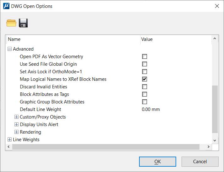
DWG Open Options Dialog, Advanced
| Setting | Description |
|---|---|
| Open PDF As Vector Geometry | If on, imports vector data available in the DWG file as design elements (eg: Lines, Line Strings, Curves, Polygons, etc.). |
| Use Seed File Global Origin | If on, uses the global origin from the DGN seed file (specified under the Basic DWG Open Options). Use this option if the DWG file originated from a DGN file, and you plan to save the file as a DGN file. |
| Set Axis Lock if OrthoMode=1 | If on, turns on
Axis
Lock if the AutoCAD
ORTHOMODE system variable is set to 1 in the DWG file.
In AutoCAD, the ORTHOMODE system variable constrains the cursor to move only horizontally and vertically. It is analogous to the Axis Lock setting in MicroStation. |
| Map Logical Names to XRef Block Names | If on, the XRef block names are used for reference
logical names in
MicroStation.
In AutoCAD, each XRef is assigned a block name. This name is typically, but not necessarily, the name of the XRef file. |
| Discard Invalid Entities | If on, then entities with invalid (abnormally large) coordinates are automatically removed when the file is saved. Almost always, these entities are a result of some sort of corruption or application error. |
| Block Attributes as Tags | If on, DWG block attributes are converted as
MicroStation tags. If off (the
default), DWG block attributes are converted as item types. A special item type
library
"DWG Attribute Definitions" is created and used
exclusively for DWG attribute definitions. Additionally, you will observe the
following behavior when the setting is off:
|
| Graphic Group Block Attributes | If on, the Graphic Group lock is turned on, so that if one element in a graphic group is manipulated, all elements in the graphic group are manipulated. The default is off. |
| Default Line Weight | Sets the default line weight to be either from the AutoCAD settings, or as a set dimension. Click on the value to open an option menu that has options of "From AutoCAD Registry" or a physical size. |
| Custom/Proxy Objects > Proxy Objects Display Mode | A proxy object is a block of data that is created with an AutoCAD ObjectARX application. This setting controls how these objects are displayed in MicroStation. |
| Custom/Proxy Objects > Custom Objects Display View | In AutoCAD applications can display different
geometry based on the view orientation. Currently,
MicroStation does not support this
and, therefore, a DWG proxy is displayed with a single representation
independent of the view orientation. This setting controls the selection of
this presentation.
|
| Custom/Proxy Objects > Custom Objects Display Mode | This setting is used to make object enablers
generate their custom objects for the desired display outcome. It has following
options:
|
| Display Units Alert | Identifies when the DWG/DXF Units alert box is
displayed.
To determine the true size of geometry within a file, MicroStation must know the linear units used in the file. Unlike DGN files, DWG and DXF files often do not have explicitly specified units. When you open a DWG file without specified units, MicroStation displays an alert box that asks you to select the file units. This alert box can be enabled or disabled for each of the following scenarios. You can also disable it by turning on Do Not Display Again. |
| Display Units Alert > Unspecified Design Center Units | If on, the units alert box is displayed if Design Center Units are selected in the Basic DWG Open Options, but the file being opened has Design Center Units set to Unspecified. |
| Display Units Alert > Decimal, Fractional, or Scientific Units | If on, the units alert box is displayed if the file being opened has Decimal, Fractional, or Scientific units. These unit settings do not imply any particular units, although meters are typically assumed. |
| Display Units Alert > Mismatched Engineering or Architectural Units | If on, the units alert box is displayed if the file being opened has Engineering or Architectural units, but the unit setting is not set to Inches. Since these file types strongly imply that inches are used, any other setting is likely to be an error. |
| Rendering | Controls how materials and light sources are used when converting to DWG. |
| Rendering > Materials | If on, the materials in a DWG file are read from the DWG file and used when the file is rendered. The default is On. |
| Rendering > Light Sources | If on, the light sources in a DWG file are read from the DWG file and used when the file is rendered. The default is On. |