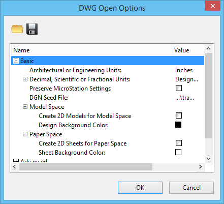
| Architectural or Engineering Units
|
Defines the linear units for
MicroStation to use when opening DWG
files with Architectural and Engineering Units (LUNITS=3 or 4). For DWG files
with these units, the linear units are inches and are displayed as feet and
inches. You should keep this option set to (MicroStation) inches unless you know that the AutoCAD
unit conventions were ignored when the file was created.
MicroStation's system for
controlling units is very flexible, but it depends on knowing the true geometry
size. In AutoCAD, the true size of geometry in a DWG file is more ambiguous.
You must set the Units options correctly to remove this ambiguity and enable
MicroStation to correctly determine
the true size of the DWG geometry. To set the units properly, you must
understand the DWG file content and the standards used to create it.
Generally, when you set units to an explicit unit
value (for example, to Inches or Meters), these units become the master units
when the DWG file is opened. The next smallest units on the units list become
the sub units. For example, if Feet are the master units, Inches are the sub
units.
However, if the units you select are either the
master or sub units of the DGN seed file, both the master and sub units from
the seed file are retained. If you want to use the sub units of the seed file
as the master units for the file that you are opening, you must change the
units in the seed file.
Values for units options include:
- Seed File Master
Units — Specifies the master units in the DGN seed file.
- Seed File Sub Units
— Specifies the sub units in the DGN seed file.
- Design Center Units
— Specifies the units used in the DWG file being opened. If the AutoCAD system
variable INSUNITS is appropriately set in the DWG file, set the units value to
Design Center Units to ensure that the units are consistent when the file is
opened in
MicroStation. Beginning with
release 2000, AutoCAD uses the INSUNITS system variable to specify units for
Design Center blocks that are inserted into existing drawings. The INSUNITS
variable allows for the type of automatic scaling that
MicroStation performs when True
Scaling is specified. However, this variable does not exist in AutoCAD files
created prior to release 2000, and may be set inconsistently in files from more
recent versions.
- Microinches
- Mils
- Inches
- Feet
- Yards
- Miles
- Micrometers
- Millimeters
- Centimeters
- Meters
- Kilometers
|
| Decimal, Scientific or Fractional Units
|
Defines the linear units for
MicroStation to use when opening DWG
files with Decimal, Scientific or Fractional Units (LUNITS=1, 2, or 5). The
unit options are the same as for files with Architectural and Engineering
Units. The default setting is
"Design Center Units".
MicroStation's system for
controlling units is very flexible, but it depends on knowing the true geometry
size. In AutoCAD, the true size of geometry in a DWG file is more ambiguous,
particularly in files with the linear units set to Decimal, Scientific or
Fractional Units. For DWG files with these units, the actual units are not
implied, but they are typically one of the metric units. Therefore, setting
this value appropriately requires some knowledge of the units used to create
the geometry in the file. If this value is not set correctly,
MicroStation may misinterpret the
size of geometry in the DWG file.
|
| Unspecified Design Center Units
|
Defines the units for
MicroStation to use when a DWG or DXF
file being opened has its Design Center Units set to
"Unspecified." The unit options are the same as
for files with Architectural and Engineering Units, except that they do not
include Seed File Master Units, Seed File Sub Units, or Design Center Units.
The default setting is Meters.
|
| Preserve
MicroStation Settings
|
If on, preserves
MicroStation-specific settings in the
DWG file.
Many
MicroStation settings do not exist
in AutoCAD, and therefore cannot be saved as settings in the DWG file. These
settings include the active angle, active scale, and default tool settings.
Some elements may also have
MicroStation-specific data, such as
a graphic group number, that does not exist in the DWG format.
Use this setting if the DWG output file will be
edited with
MicroStation, and you want to
preserve the settings and element data between editing sessions.
MicroStation-specific settings are
saved to an XRECORD entity, and
MicroStation-specific element data
is saved as XDATA on each entity.
If the output file will not be edited with
MicroStation, then this data is not
required, and is ignored by other applications.
|
| DGN Seed File
|
Sets the path and the filename of the seed DGN
file. To browse for this file, click the Value column.
When a DWG file is open,
MicroStation extracts most of the
settings directly from the DWG file. However,
MicroStation settings that are not
present in the DWG are extracted from the DGN seed file. These settings may
include default values for all
MicroStation tool settings, active
angle, active scale, tentative point display mode, and view attributes such as
text nodes on/off.
A DWG file does not have unit resolution. When a
DWG file is opened in
MicroStation, the resolution in the DGN seed
file is used. You may set resolution in your DGN seed file for opening a DWG
file. When saving a DGN file to DWG, the same resolution in the seed file will
be used upon opening the DWG in
MicroStation. Therefore your original
resolution may be different.
In general, the storage Resolution value in the
seed file is insignificant. This setting determines the number of positional
units per AutoCAD unit. The default seed file uses a storage resolution of
10000.
|
|
|
If on, creates a 2D model to represent model space.
Use this setting when you know that the model contains only 2D geometry in the
XY plane. If 3D geometry is present, it is flattened to the XY plane.
|
|
|
Opens the Select RGB color dialog, which is used to
set the background color that
MicroStation uses for the design model
("model space").
|
|
|
If on, creates 2D sheet models to represent paper
space sheets. Use this setting when you know that the paper space models
contain only 2D geometry in the XY plane. If 3D geometry is present, it is
flattened to the XY plane. Note that the viewports of a 2D sheet model can
contain views of 3D models, so it is not necessary to have 2D models to use 2D
sheets.
|
|
|
Opens the Select RGB color dialog, which is used to
set the background color of the sheet model ("layout").
|