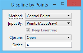
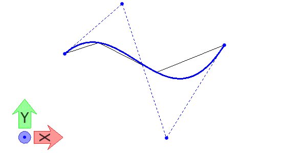
| Method |
Sets the manner in which the curve is generated (see large table above). |
| Input By |
Sets the manner in which the input points are located.
- Points (AccuDraw) — The curve is placed by entering data points, using AccuDraw.
- Picking Line String — The curve is constructed based on the vertices of an selected line string or complex chain (results in open B-spline) or shape or complex shape (results in closed B-spline).
|
| Keep Line String |
(Input By set to Picking Line String only) If on, the line string is retained in the model. |
| Closure |
Sets whether the curve is Open or Closed. Not available if Method is Catmull-Rom. |
| Order |
(Method set to Control Points or L-Square By Num only) Sets the order of the equation that defines the curve (2-15). |
| Poles |
(Method set to L-Square By Num only) Sets the number of poles (3–5000). |
| Tolerance |
(Method set to L-Square By Tol. only) Sets the fitting or approximation tolerance. The distance from any one of the input data points to the curve is less than this value. The distance is computed by projecting a point to the curve. |
| Tangents |
(Method set to Through Points or L-Square By Tol and Closure set to Open only) Sets the manner in which the curve's tangency to adjacent elements is controlled.
- None — Default tangent directions are automatically computed.
- Both — Starting and ending tangent directions are defined graphically.
- Start — Starting tangent direction is defined graphically.
- End — Ending tangent direction is defined graphically.
|
| Through End Points |
(Method set to L-Square By Tol only) Sets the manner in which the curve's beginning and ending points are located. If On, the curve passes through the first and the last input points. Otherwise, the curve's endpoints are computed based on the Tolerance setting.
|
| Fill Type |
(Closure set to Closed only) Sets the Active Fill Type.
- None - If on, the complex shape is not filled.
- Opaque - If on, the complex shape is filled with the Active Color.
- Outlined - If on, the complex shape is filled with the Fill Color.
|
| Fill Color |
(Closure set to Closed only) Sets color with which the element(s) are filled. To define the Fill Color, use the controls on the Active Color, True Color, Color Book, or Gradient Fill tab.
- If Fill Type is Opaque, the element(s) are filled with the Active Color, which is also the color of the element's outline.
- If Fill Type is Outlined, the element(s) can be filled with a color that is different from the Active Color.
|
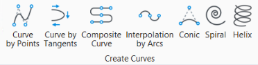
 Used to place a B-spline curve.