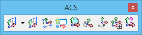
ACS Toolbox
The tools in the ACS toolbox are used to define and manipulate an auxiliary coordinate system (ACS) — a coordinate system you define that differs from the design plane (world) and view coordinate systems. For general information about using an ACS, see 3D auxiliary coordinate systems.
One ACS can be active at any time in a 2D or 3D design. While ACSs can be used in 2D, they are most useful in 3D design.
Note: All tools in a toolbox are not always visible by default. To see all tools, right-click in the toolbox and select Show All from the menu.
| To | Select in the ACS toolbox |
|---|---|
| Open the Auxiliary Coordinates dialog. | Auxiliary Coordinates |
| Define an ACS on 2D elements and on 3D elements including surfaces, solid faces, and mesh facets. | Define ACS (Aligned with Element) |
| Define an ACS by entering data points. | Define ACS by Points |
| Assign an Auxiliary Coordinate Systems to each view. | Define ACS by View |
| Define an ACS aligned with a reference. | Define ACS by Reference |
| Rotate the active ACS. | Rotate ACS |
| Move the origin of the Active ACS. | Move ACS |
| Apply the ACS to a selected view or all views. | Apply ACS to Selected View |
| Identify an ACS for attachment as the Active ACS. | Select ACS |


