Apply Clip Volume
 Used to limit the
displayed volume for a view to the region within a clipping element. This is
useful for working within a limited volume of a model without being hindered by
geometry outside the region of interest. When a clip volume is applied to
a view, only elements that are located within the clip volume will display, or
can be snapped to, in that view. Each view may have a different clip volume
applied.
Used to limit the
displayed volume for a view to the region within a clipping element. This is
useful for working within a limited volume of a model without being hindered by
geometry outside the region of interest. When a clip volume is applied to
a view, only elements that are located within the clip volume will display, or
can be snapped to, in that view. Each view may have a different clip volume
applied.
You can access this tool from the following:

Operations, such as view rotation, fence processing, visible edges display, and rendering, honor the clip volumes. They ignore any elements that are not displayed within the defined volume for the view.
Clipping elements may consist of any solid (other than spheres or feature solids) or closed extrusion, cylinders, or closed planar elements (shapes, circles, ellipses, complex shapes, grouped holes). Where a planar element is chosen, or you use the clipping elements by points options, the clipping volume is generated by sweeping the planar element through the entire model. Planar elements may be selected in any view, because the sweep direction is orthogonal to the plane of the element. Similarly, clip elements that you define by points may be drawn in any view (AccuDraw can be used to set the correct orientation of the clip element).
If you later move, or modify a clipping element, then the clip volume is moved or modified also. If you delete a clipping element, then the clipping is removed also. Clipping elements can be manipulated/modified with the standard MicroStation tools. Refer to Clip volume edit handles for modifying the clip volume.
When you clip open elements such as lines and arcs, their intersecting points are displayed in the Cut display.
Once a clip volume has been applied to a view, you can change the clip volume's settings in the Clip Volume Settings section of the View Attributes dialog. The shadows in a clip volume are visible only when the display styles in the Clip Volume Settings section of the View Attributes dialog are set to From View and the view’s display style has shadows turned on. You can hide or display the clip element via the Show or Hide Clip Volume tool.
The Section Clip icon create a clip volume along the section plane. The entire model is clipped to half along the selected section plane. The fitted sections are elements. You can manipulate them using the standard element manipulation tools. To orient the fitted section to the ACS, turn on the ACS Plane Lock.
You can create steps in the fitted section. The steps created can be merged using step handles provided on the steps.
The name of the tool settings window changes with the selection of icon in it. For example, if you click the icon Apply Clip Volume by 2 Points, the window name changes to Define Clip Volume by 2 Points.


Apply Clip Volume tool settings window when Apply Clip Volume By Element, Apply Clip Volume By 2 Points, or Apply Fitted Clip Volume icon is selected
| Setting | Description |
|---|---|
| Apply Clip Volume By Element | Applies a clip volume from an existing element. |
| Section Clip Tools | Lets you apply a clip volume by defining a clipping plane with two data points. The clipping volume is created by sweeping the defined clipping element through the entire model. |
| Apply Clip Volume By 2 Points | Lets you apply a clip volume by interactively defining a rectangular clipping element with two data points. The clipping volume is created by sweeping the defined clipping element through the entire model. |
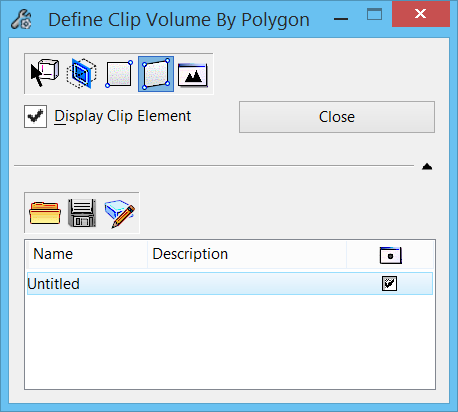
| Apply Clip Volume By Polygon | Lets you apply a clip volume by interactively defining vertices of a polygon with data points. The polygon can be closed by entering a data point at the start point, or by clicking the Close button. The clipping volume is created by sweeping the defined clipping element through the entire model. |
| Apply Fitted Clip Volume | Applies a clip volume that encloses all the elements in the model. |
| Apply Fitted Section Parallel to the Top Plane | Place the fitted section parallel to the top plane. |
| Apply Fitted Section Parallel to the Front Plane | Place the fitted section parallel to the front plane. |
| Apply Fitted Section Parallel to the Side Plane | Place the fitted section parallel to the side plane. |
| Apply Clip By Section Plane | Place fitted section along the plane created by two data points. |
| Display Clip Element | If on, the clip element remains displayed after creating the clip volume for the view. Display of this element can be turned on or off later, with the Show or Hide Clip Volume Element icon. |
| Drawing Seed | Defines the seed file from which the detailing symbol style will be used for the clip volume. |
| Close button | (Apply Clip By Polygon only) Closes the polygon clipping element. |
| Tolerance | (Available only when a point cloud is referenced in the model) Allows you to enter the maximum distance, in working units, from each side of the cut plane to points that will be considered as part of the plane. |
| Project Points to Cut Plane | (Available only when a point cloud is referenced in the model) If on, the points within the specified tolerance range will be projected on the cut plane. If off, the points will be displayed at their real 3D location. |
| Expand | Expands the tool settings to reveal the named fence tools. |
| Named boundary tools | Clicking the Expand arrow expands the tool settings
to reveal the named boundary tools.
|


 Apply Clip Volume — Creates a
clip volume from the named boundary (selected from the list box), and applies
the clip volume to the active view.
Apply Clip Volume — Creates a
clip volume from the named boundary (selected from the list box), and applies
the clip volume to the active view.
 Create Named Boundary from Clip
Volume — (Clip volume in active view only) Creates a named boundary from the
clip volume.
Create Named Boundary from Clip
Volume — (Clip volume in active view only) Creates a named boundary from the
clip volume.
 Named Boundaries — Opens the