Place Drawing Boundary
 Used to place a
drawing boundary in a model.
Used to place a
drawing boundary in a model.
You can access this tool from the following:

If you place a drawing boundary in a DGNLib file, it can be used for placing named boundaries in your model.
The drawing boundary consists of a boundary and an annotation. The annotation contains the fields or label and a drawing line. The annotation is always aligned to the sheet’s bottom. If you rotate the reference linked to the drawing boundary, the annotation will not rotate and will remain aligned to the sheet’s bottom. Also, when you rotate the reference the annotation will compute its boundary to cover the entire reference.
You can adjust the length of the drawing line in the annotation by selecting its edge and dragging it. The length of the drawing line can also be controlled by the Underline settings in the Detailing Symbol Styles dialog.
You can update the Detail Scale field in the drawing boundary using the key-in DRAWINGTITLE UPDATE ALL.
| Setting | Description |
|---|---|
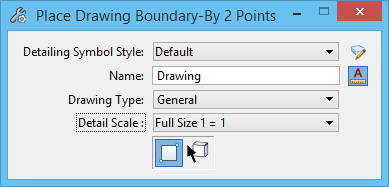
| Detailing Symbol Style | Defines the detailing symbol style to be used for the drawing boundary. |
| Show Detailing Symbol Style Settings (icon) | Opens the Detailing Symbol Styles dialog, in which you can create or edit a detailing symbol style. |
| Name | Defines the name of the drawing boundary. The default name is D 1 and is incremented by one each time drawing boundary is placed. The default name may be edited as required. |
| Annotation Scale (icon) |
Used to turn on annotation scale. When this lock is on, the
annotation scale is applied to drawing boundary.
By default, the annotation scale is taken from the model's Annotation Scale setting. You can change it only in the model's properties in the Properties dialog. The exception is when the model's Propagate Annotation Scale property is off. In that case, the annotation scale can be controlled independently for each element via its properties. |
| Drawing Type | Sets the type of drawing boundary to be created. Options are General, Section, Elevation, Detail, and Plan. |
| Detail Scale | Sets the scale at which the drawing boundary is placed. |
| By 2 Points | Lets you create the drawing boundary by interactively defining a rectangular boundary with two data points. |
| By Element | Lets you create a drawing boundary from an existing closed element. |


