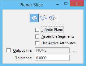
Planar Slice
 Used to generate a planar section through design geometry, using as a cutting plane an existing planar element, a plane defined by three points, or a plane perpendicular to a view and defined by two points.
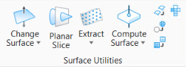
You can access this tool from the following:
| Setting | Description |
|---|---|
| Slice By Element icon | Lets you select a planar element that is used as a cutting plane to create a section. |
| Slice By Three Points icon | Lets you define a cutting plane with three points. |
| Slice By View icon |
Lets you draw a line in a view, which defines the location of a cutting plane perpendicular to the view. For example, you could define the cutting plane along the X or Y axis in a top view, which would create section elements that could be viewed in Front or Right views. |
| Infinite Plane | If on, then the selected or defined section plane is extended throughout the model. |
| Assemble Segments | If on, adjacent (touching) individual lines of a generated section are assembled together as a line string. |
| Use Active Attributes | If on, the section is created with the element using the active attributes. If off, the section is created with the element taking the attributes of the profile element. |
| Output File | If on, click the Browse Another Destination File icon to open the Open Section Output File dialog, which lets you specify a file into which the sections will be placed or create a new file. |
| Tolerance | Sets the tolerance for the generated slice element. |


