Solid by Extrusion Along Path

- a solid by extruding a profile element along a path. Profile elements can be a closed element such as a shape, complex shape, B-spline surface, or a selected face of solid or surface element.
- a tubular solid extrusion along a path.
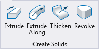
You can access this tool from the following:
Prior to accepting the construction, the result is displayed along with graphics that let you adjust the scale origin point (if scaling is enabled) and the direction of the extrusion.
| Setting | Description |
|---|---|
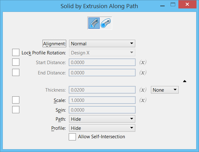
| Custom Profile | Creates a solid by extrusion along a curve. |
| Circular Profile | Creates a tubular solid by extrusion along a curve. For details, refer to the topic Solid By Extrusion Along Path - Circular Profile |
| Alignment | Determines the orientation of the profile element as it is extruded. |
| Lock Profile Rotation | If on, lets you define the direction for the
orientation of the profile as it is extruded along a non-planar path.
If off, the orientation of the profile is controlled by the geometry of the non-planar path, possibly causing unwanted twisting. |
| Start Distance | Lets you define the distance at which the extrusion will start, along the path element. You can change this graphically by clicking and dragging the starting distance control point. |
| Variable Link | Let's you use an existing variable to set the input value, defined in the Variables dialog. |
| End Distance | Lets you define the distance at which the extrusion will end, along the path element. You can change this graphically by clicking and dragging the ending distance control point. |
| Thickness | Sets the wall thickness when a hollow solid, or a
surface with thickness is required.
|
| Scale | Lets you apply a scale factor to the extrusion. The profile is scaled about the selected scale point as it is extruded. Prior to accepting the extrusion, you can adjust the scale point by dragging the scale point graphic (sphere) to a new location. |
| Spin | If on, the profile is rotated by the angle specified in the angle field as it is extruded along the path. |
| Path | Sets the behavior of the path after the feature is
created.
|
| Profile | Sets the behavior of the profile after the feature
is created.
|
| Allow Self-Intersection | Allows geometry that will intersect with itself to be created. If on, the creation of intersecting geometry can take a long time. |


