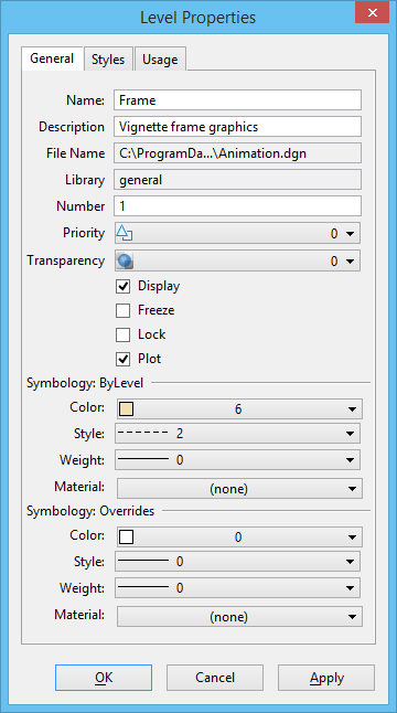
| Name |
Lists the name of the selected level. |
| Description |
Lists a description of the selected level. |
| File Name |
Lists the name of file that the selected level is from. This file can be a reference or a level library. |
| Library |
Lists the name of a library file, if one is used. |
| Number |
Lists the level number. Note: Level numbers are not supported in DWG workmode.
|
| Priority |
(2D models only) Identifies the level display priority value. A level with the highest priority value displays in front, while a level with the lowest priority value displays in back. Reference and element priority values also affect the display.
LEVEL
SET
PRIORITY
[
new-level-priority [file:file-spec] level-spec
]
|
| Transparency |
Identifies the level transparency value. A value of 0 indicates no transparency and a value of 100% indicates almost complete transparency.
LEVEL
SET
TRANSPARENCY
[
new-level–transparency [file:file-spec] level-spec
]
|
| Display |
If on, turns on global display of the level. If off, the elements on the level are not displayed. However, if a cell placed on the level has elements in other levels, those elements are displayed. |
| Freeze |
If on, freezes the selected level. When a level is frozen, elements on the level are not displayed. If a cell placed on the level has elements on other levels, none of the elements are displayed. |
| Lock |
If on, elements on this level cannot be edited. |
| Plot |
If on, elements on this level can be printed. If off, the elements cannot be printed. |
| Symbology: ByLevel |
Lists default settings for level symbology (Color, line Style, line Weight, Material). When an element that uses ByLevel symbology is placed on the level, the element uses the symbology settings assigned to the level.
LEVEL
SET
BYLEVEL
COLOR
[
color–spec
]
[
file:file–spec
]
[
level–spec
]
LEVEL
SET
BYLEVEL
STYLE
[
style–spec
]
[
file:file–spec
]
[
level–spec
]
LEVEL
SET
BYLEVEL
WEIGHT
[
weight–spec
]
[
file:file–spec
]
[
level–spec
]
LEVEL
SET
BYLEVEL
MATERIAL
[
material–spec
]
[
file:file–spec
]
[
level–spec
]
|
| Symbology: Overrides |
Lists override symbology (Color, line Style, line Weight, Material) settings, which are view-dependent alternate settings for level symbology. When an element is placed on the selected level, it uses the symbology settings assigned to the level. To enable the view override settings, open the View Attributes dialog and turn on Level Overrides.
LEVEL
SET OVERRIDE COLOR
<
OFF |
ON |
TOGGLE
>
[
color-spec
]
[
file:file–spec
]
[
level–spec
]
LEVEL
SET OVERRIDE STYLE
<
OFF |
ON |
TOGGLE
>
[
style-spec
]
[
file:file–spec
]
[
level–spec
]
LEVEL
SET OVERRIDE WEIGHT
<
OFF |
ON |
TOGGLE
>
[
weight-spec
]
[
file:file–spec
]
[
level–spec
]
LEVEL
SET OVERRIDE MATERIAL
<
OFF |
ON |
TOGGLE
>
[
material-spec
]
[
file:file–spec
]
[
level–spec
]
Note: Symbology overrides are disabled in DWG workmode. All elements are displayed with ByLevel symbology.
|