Selecting Faces on a Solid
When you are working with feature-based solids the screen pointer will, by default, select only those faces that would be visible to you in the view. That is, it ignores surfaces that would, in real life, be obscured by the rest of the solid in the view. Consider a rectangular slab feature, viewed in an Isometric view. By default, only the top, front, and left faces of the slab would highlight as you pass the pointer over it.
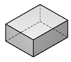
By default, the pointer selects only those surfaces that would be visible in the view in real life, such as the shaded surfaces in the diagram.
In wireframe display mode, where all faces are visible, it is convenient to be able to work on any face of the solid, whether or not it would be hidden in real life. MicroStation provides a means for doing just this. For example, to select a face(s) at the rear of the example slab, after selecting it, you first snap to a common edge or vertex and then move the pointer to highlight the required face prior to accepting with a data point. After the snap point on the edge or vertex, only faces sharing that common edge or vertex will be highlighted by the pointer.
