Standard Workflow for Using Named Presentations
- In a model, draw the desired 3D model. For example, a door.
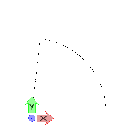
- In a different view orientation, place elements that you want to view for the model in that view orientation. For example, for a door model, in the Top view, you will draw the commonly used symbol of door in plan view, which is a rectangle with an arc and line indicating the door and its swing.
-
Select the
Parametric Components dialog
().
The Parametric Components dialog opens.
- Select the Named Presentations tab.
-
Select the element(s) you wish to add to a named presentation.
In our example, select the door symbol in Top view.
-
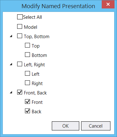
Select Modify.

- Turn on the checkbox(s) corresponding to desired views to which you want to add the element(s).
- Enter a data point to accept. The elements are added to the selected named presentation.
- Now place the model as a parametric cell in another DGN.
- In the View Attributes dialog in the DGN where you have placed the parametric cell, make sure the Named Presentation view attribute is turned on.
- Change the orientation to the one that has named presentation created and observe that the elements that you included for that named presentation are displayed instead of the original cell. So, in our door example, in the Top view, you will see just the door symbol, which is a rectangle with an arc and line.