Changing the Order of Features
When you create a solid with features, the order in which the features are created can be important. This can be demonstrated with a simple example. In this example, the solid is constructed from four slabs, one of which has a "through" cut in it. The slabs are merged into a single solid with the Union Feature tool.
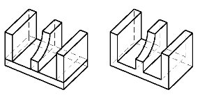
Even though the cut through the center (vertical) slab is a "through" cut, it does not extend to the rest of the solid after the union with the other slabs. Looking at the feature tree for the solid, you can see that the reason for this is that the cut is associated only with Slab (2).

For the cut to extend through the other parts of the merged solid, it would have to be created after the union. In a situation like this, you could extract the profile used for the cut. This then could be used to cut through the rest of the solid. A simpler method, however, is to reorder the feature tree, with the cut placed above the Union Solids entry. In this case, the union currently is at the top of the feature tree, so we need to relocate the cut to the top.