| Efficiency |
Lets you define the efficiency of the material directly, either by adjusting the slider, or by keying in a value in the associated field. Efficiency is defined as the total percentage of incoming light that is re-transmitted back into the environment. This includes diffuse and specular reflections, as well as the light transmitted through opacity and translucency. When the efficiency is 100% or greater, it is displayed in red, warning that the material is unrealistic. Typical materials in the real world generally range in efficiency from 30% to 70%. |
| Lock icon (efficiency) |
Clicking the icon toggles the lock on and off.
If on (locked), the efficiency of the material is locked such that modifying the diffuse, specular, opacity, or translucency components will automatically adjust the other components to maintain the efficiency value.
If off (unlocked), modifying the diffuse, specular, opacity, or translucency components changes the efficiency value, but does not automatically adjust the other components.
|
| Color button |
Defines the color used for the material when rendered. Clicking the arrow icon opens a menu with the following options:
- Custom — Uses the custom color. You can define the custom color by clicking the color button to open the Base Color dialog, which lets you define the color. When Custom is selected, the color button displays the selected Base Color.
- Use element color — Uses the color of the element in the model.
|
| Color scale |
Specifies the percentage of the pattern map that is used in the material. Values range from 0 (solid color with no pattern map) to 100 (entirely pattern map) and may be typed in the text field or adjusted using the slider. |
| Pattern map icon |
Defines whether or not a pattern map is used by the material. Click the arrow icon to open a menu with the following options:
- On — A pattern map, if defined, will be used in the material. Pausing the pointer over the pattern icon displays the name of the current pattern map.
If a pattern map is defined, click this icon to open the Map Editor dialog opens, which lets you edit the settings for the pattern map. This includes options for selecting an image file, a procedure, or a gradient. If a pattern map is not defined, clicking this icon opens the Open Image file dialog, which lets you select an image file for use as a pattern map.
- Off — No pattern map will be used by the material.
|
| Diffuse |
Defines the percentage of incoming light that is reflected in all directions equally. This affects the overall brightness of the material. |
| Diffuse scale |
Specifies the percentage of diffuse map that is used in the material. Values range from 0 (dark) to 100 (bright) and may be typed in the text field or adjusted using the slider. |
| Diffuse map icon |
Defines whether or not a diffuse map is used by the material. Click the arrow icon to open a menu with the following options:
- On — A diffuse map, if defined, will be used in the material. Pausing the pointer over the diffuse icon displays the name of the current diffuse map.
Click the icon to open the Open Image file dialog, which lets you select an image file for use as a diffuse map. After selecting the image file, the Map Editor dialog opens, which lets you edit the settings for the diffuse map. This includes options for selecting an image file, a procedure, or a gradient.
The Diffuse amount map acts as a multiplier for the diffuse color setting. Applying a diffuse map gives an effect where the material has no diffuse reflectance where the pixels of the map are black, up to the amount specified in the material where the pixels are white. A diffuse map can be used in conjunction with a pattern map to give more contrast to the diffuse reflection.
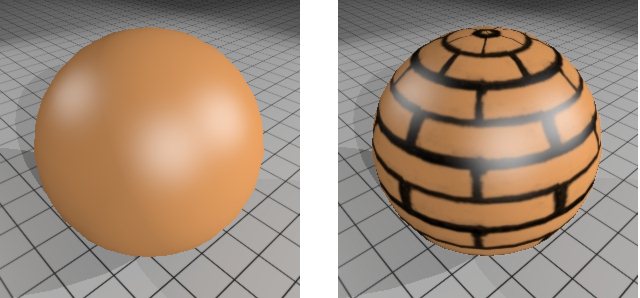
Material with no diffuse map (left) and with simple grayscale brick texture diffuse map (right)
- Off — No diffuse map will be used by the material.
- Link to pattern | bump | specular | reflect | opacity | translucency | finish — Links Diffuse mapping to the selected map or setting.
- Unlink — (Available only if the Diffuse map currently is linked another map or setting) Lets you unlink the Diffuse setting.
|
| Cast Shadows |
If enabled, the material can cast shadows. If disabled, no shadows are cast by the material. |
| Geometry map icon |
Defines whether or not a geometry map is used by the material. Click the arrow icon to open a menu with the following options:
- On — A geometry map, if defined, will be used in the material. Pausing the pointer over the geometry map icon displays the name of the current geometry map.
Click the icon to open the Cell Library dialog, which lets you select a cell for use as a geometry map. After selecting the cell, the Map Editor dialog opens, which lets you edit the settings for the geometry map.
- Off — No geometry map will be used by the material.
- Link to pattern | bump | specular | reflect | opacity | translucency | finish | diffuse — Links geometry mapping to the selected map or setting.
|
| Specular color icon |
Defines the specular highlight and opacity color. Clicking the arrow icon opens a menu with the following options:
- Plastic — Specular highlights and opacity color will be white.
- Metallic — Specular highlights and opacity color will be the same color as the base material.
- Use Element — Specular highlights and opacity color will be the same color as the element.
- Color Map — Specular highlights are defined by a texture map.

Specular colors with no map (left) and with map defined (right)
- Custom — Available only if a custom color has been specified (by clicking the specular color button to open the Specular Color dialog, which lets you define a custom color). When a custom color has been defined, the button displays the custom color.
|
| Specular scale |
Defines the percentage of incoming light that is reflected in the opposite direction of the incoming light. Values may range from 0 (dull) to 100 (shiny) and may be keyed in to the text field, or adjusted using the slider. |
| Specular map icon |
(Enabled only when Specular has a value greater than zero) Lets you link specular to a map or other settings. Click the arrow icon to open a menu with the following options:
- On — A pattern map, if defined, will be used with Specular. Pausing the pointer over the pattern icon will display the name of the current pattern map.
Click the icon to open the Open Image file dialog, which lets you select an image file for use as a specular pattern map. After selecting the image file, the Map Editor dialog opens, which lets you edit the settings for the pattern map. This includes options for selecting an image file, a procedure, or a gradient.
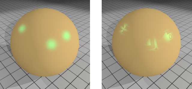
Specular material without map (left) and with map (right)
- Off — Turns off Specular mapping.
- Link to pattern/bump — Links Specular mapping to the current pattern map or bump map.
- Unlink — (Available only if the Specular map currently is linked another map or setting) Lets you unlink the Specular setting.
|
| Finish icon |
(Visible only when additional specular properties are displayed) Defines how the roughness of the surface material is calculated. Clicking the button opens a menu with the following options:
- Custom — Lets you set a value for Finish. Values can range from 1 (Rough) to 100 (Smooth).
- Off — No specular highlights are visible.
- Linked to specular — Links Finish to the setting for Specular so that modifying the Specular setting produces the same modification in the Reflect setting.
|
| Finish scale |
(Visible only when additional specular properties are displayed) Defines the roughness of the material surface. Small values result in rough surfaces with large specular highlights. Large values result in smooth surfaces with narrow specular highlights. Can vary from 1 (Rough) to 100 (Smooth). |
| Finish map icon |
(Enabled only when Finish is set to Custom and has a value greater than zero) Lets you link Finish to a map or other settings. Click the arrow icon to open a menu with the following options:
- On — A pattern map, if defined, will be used with Finish. Pausing the pointer over the pattern icon displays the name of the current pattern map.
Click the icon to open the Open Image file dialog, which lets you select an image file for use as a pattern map. After selecting the image file, the Map Editor dialog opens, which lets you edit the settings for the pattern map. This includes options for selecting an image file, a procedure, or a gradient.
- Off — Turns off Finish mapping.
- Link to pattern/bump/specular/reflect/opacity/translucency — Links Finish mapping to the current pattern or bump map, or to the setting for specular, reflect, opacity, or translucency.
- Unlink — (Available only if the Finish map currently is linked another map or setting) Lets you unlink the Finish setting.
|
| Reflect icon |
(Visible only when additional specular properties are displayed) Defines how the amount of reflection is calculated. Clicking the button opens a menu with the following options:
- Link to Specular — Links Reflect to the setting for Specular so that modifying the Specular setting produces the same modification in the Reflect setting.
- Color Map — Reflection are defined by a texture map.
- Custom — Lets you define a value for Reflect that is less than that of Specular (Reflect cannot exceed the value of Specular).
|
| Reflect scale |
(Visible only when additional specular properties are displayed) Enabled only when Reflect is set to Custom. Defines the amount of incoming light from other objects in the scene that is reflected. Can vary from 0 (None) to 100 (Full) but must be a value less than or equal to the value for Specular. Values may be keyed in to the text field, or adjusted using the slider. |
| Reflect map icon |
(Enabled only when Reflect is set to Custom and has a value greater than zero) Lets you link reflect to a map or other settings. Click the arrow icon to open a menu with the following options:
- On — A pattern map, if defined, will be used with Reflect. Pausing the pointer over the pattern icon displays the name of the current pattern map.
Click the icon to open the Open Image file dialog, which lets you select an image file for use as a pattern map. After selecting the image file, the Map Editor dialog opens, which lets you edit the settings for the pattern map. This includes options for selecting an image file, a procedure, or a gradient.
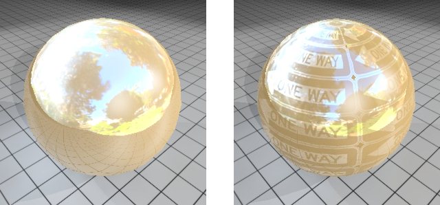
Reflective material without map (left) and with map (right)
- Off — Turns off Reflect mapping
- Link to pattern/bump/specular — Links Reflect mapping to the current pattern or bump map, or to the specular setting.
- Unlink — (Available only if the Reflect map currently is linked another map or setting) Lets you unlink the Reflect setting.
|
| Fresnel icon |
Defines how the Fresnel of the surface material is calculated.
- Custom — Lets you define a value for Fresnel that is less than that of Specular (Reflect cannot exceed the value of Specular).
- Link to reflect — Links Fresnel to the setting for Specular so that modifying the Specular setting produces the same modification in the Reflect setting.
|
| Fresnel scale |
The Fresnel value increases the specular value when light hits a surface at a glancing angle. Increasing this value results in a large specular value at glancing angles. |
| Fresnel map icon |
Lets you link Fresnel to a map or other settings. Click the arrow icon to open a menu with the following options:
- On — A Fresnel map, if defined, will be used. Pausing the pointer over the icon displays the name of the current map.
Click the icon to open the Open Image file dialog, which lets you select an image file for use as a map. After selecting the image file, the Map Editor dialog opens, which lets you edit the settings for the map.
- Off — Turns off Fresnel mapping.
- Link to — Drop-down menu lists many options to which you can link Fresnel mapping.
|
| Blur Reflections |
(Reflect greater than zero only) If enabled, reflections visible in the material are blurred. The amount of blurring is controlled by the Finish setting.
Reflective material with Blur Reflections disabled (left) and enabled (right)
|
| Reflection Rays |
(Blur Reflections enabled only) Sets how many reflection rays are used to create the blurring. Increasing the number of rays can improve the image but it will take longer to render. |
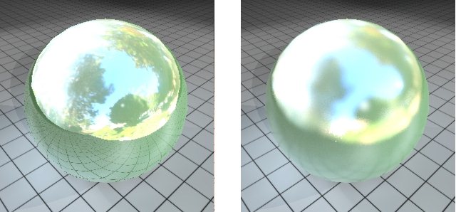
| Clearcoat scale |
Produces a clearcoat lacquer effect on the material, which lets you create very realistic automotive paints and other finishes where a layer of clear coating is applied to a base coat material. The Clearcoat slider goes from 0 (None) to 100 (Full), with good results for most automotive paints at around 30 to 60. You can key-in values above 100, which will produce even thicker clear coating.
Note: When adding a clearcoat layer, Reflect should be set to zero since the basecoat is essentially the pigment (color) layer. Adding clear coating will result in a reflective finish.

Material with no clearcoat (left) and with clearcoat applied (right)
|
| Clearcoat map icon |
Lets you select a clearcoat map, or link clearcoat to other settings. The clearcoat map changes the perceived thickness of the clearcoat lacquer effect. Black pixels in the map will apply a 0% clearcoat, and white pixels will apply the clearcoat value defined in the material.

Clearcoat with simple brick pattern map
- On — A pattern map, if defined, will be used with clearcoat. Pausing the pointer over the pattern icon will display the name of the current pattern map. Click the icon to open the Open Image file dialog, which lets you select an image file for use as a pattern map. After selecting the image file, the Map Editor dialog opens, which lets you edit the settings for the pattern map. This includes options for selecting an image file, a procedure, or a gradient.
- Off — No pattern map will be used with clearcoat.
- Link to pattern | bump | specular | reflect | opacity | translucency | finish | diffuse | glow — Links clearcoat to the selected setting.
- Unlink — (Available only if the Clearcoat map currently is linked another map or setting) Lets you unlink the Clearcoat setting.
|
| Anisotropy scale |
Controls the direction of the "scratches" on the surface. Values vary from -100% to +100% with the following results:
- -100% emphasizes the highlights toward the horizontal direction.
- +100% emphasizes the highlights toward the vertical direction.

Images showing the change in anisotropy from -100% to +100%.
|
| Anisotropy map icon |
Lets you specify an anisotropy map to vary the anisotropic direction. Where the anisotropy map is:
- Bright — highlights are stronger in the vertical direction.
- Dark — highlights are stronger in the horizontal direction.

Material showing effects from an anisotropy map
- On — Turns on the anisotropy map (where one has been defined).
- Off — Turns off a previously defined anisotropy map.
- Link to pattern | bump | specular | reflect | opacity | translucency | finish | diffuse | glow | clearcoat | anisotropy — Uses whatever is defined for the selected map — Nothing, Image, Gradient, or Procedure.
- Unlink — (Available only if the displacement map currently is linked to another map) Lets you unlink the anisotropy map.
|
| Bump scale |
Enabled only when a bump map has been specified for the material. Controls the bumpiness caused by the bump map. Values may be entered in the text field, or adjusted with the slider. Higher the value more will be the bumpiness.
Example without (left) and with bump map applied (right)
|
| Bump map icon |
Where no bump map has been defined previously, opens the Open Image File dialog, which lets you select an image file to use as a bump map. Click the arrow icon to open a menu with the following options:
- On — Turns on the bump map (where one has been defined).
- Off — Turns off a previously defined bump map.
- Link to Pattern — Bump map uses whatever is defined for the pattern map.
- Unlink — (Available only if the bump map currently is linked to the pattern map) Lets you unlink the bump map from the pattern map.
|
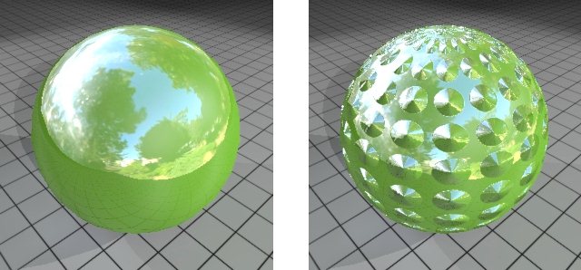
| Displacement (mm) |
(Displacement map applied only) Sets the maximum distance that a displacement map is displaced. |
| Displacement map icon |
Where no displacement map has been defined previously, opens the Open Image File dialog, which lets you select an image file to use as a displacement map.
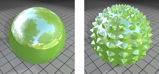
Example without (left) and with (right) displacement map
Click the arrow icon to open a menu with the following options:
- On — Turns on the displacement map (where one has been defined).
- Off — Turns off a previously defined displacement map.
- Link to pattern | bump | specular | reflect | opacity | translucency | finish | diffuse | glow | clearcoat | anisotropy — Uses whatever is defined for the pattern map — Nothing, Image, Gradient, or Procedure.
- Unlink — (Available only if the displacement map currently is linked to the pattern map) Lets you unlink the bump map from the pattern map.
|
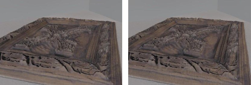
| Normal Map |
Lets you define a normal map for a material. The map may be selected individually, or linked to another map via the option menu. A normal map allows the surface normal of a polygon to be completely defined by an image. Similar to bump mapping, a normal map perturbs the surface normal. Normal maps replace the surface normal at every point on the surface. This allows lower polygon models to be used but to keep the detail of the surface normals as if a more complex model is used. This can be seen in the images below where, due to the normal map, the image on the right has better shadow definition than the image on the left, especially in areas of low displacement.
|
| Glow icon |
Lets you define a glow color or to link glow to other settings.
- Link to diffuse — Links glow color to the base color/map.
- Link to specular — Links glow color to the specular settings.
- Color map — The glow color is defined by a color map. Click on the icon to select or modify the color map.
- Custom — Lets you select a glow color, which is displayed in the icon. Click on the icon to define or modify the custom color.
|
| Glow |
Defines the amount of light the material appears to emit. This value adds to the overall reflectance of the material, independent of the amount of incoming light. Click the option menu button to the right to select from a range of values for common light emitting objects.
|
| Glow map icon |
Lets you specify a glow map for the material. Glow map may also be linked to the Pixels in a glow map specify the fraction of glow emitted by the surface at that point up to 100%, which uses the value of glow defined in the material. In the example image following, the glow map is a white background (100% glow value) with black lettering and border.

Example using a glow map having a white background (100% glow value) with black lettering and border
|
| Preview |
Contains controls for displaying a preview of the material being defined/edited. |