Profile Runs have several uses:
For hydraulic (i.e. storm or sanitary) networks, you can
view hydraulic information such as the hydraulic and energy grade lines. If the
system has been analysed using a dynamic wave solver, then these lines are
time-dependant.
For any profile run, you can view a section through a
selected terrain model or surface, which helps you to get an appreciation for
the depth of cover.
You can project a profile run onto a linear element, such
as a road centreline, so you can judge whether the slopes of the conduits are
in the same direction and magnitude as the road or track design. You can
project a profile run onto another profile run, to check that a storm or
sanitary system is below a water distribution system, for example.
Project Run works by raising a normal from the start and
end of each conduit to the linear element. The length of each conduit can
therefore appear to increase or decrease. In an extreme situation, where a
conduit crosses a road for example, the length of the conduit could be
significantly reduced.
Once they have been created, profile runs are shown in the
Explorer, in the Drainage and Utilities Model category.
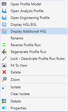
Right-click on the profile run of interest to display a pop-up menu, from which
you can view, rename, or delete the profile.
Display Additional
HGL's on Profile
Drainage (i.e. storm or sanitary) conduits include
information on the Hydraulic Grade Line and the Energy Grade Line. This
information is for the current scenario, and is automatically updated as the
scenario is computed, or the current scenario is changed. If the user wants to
display additional/multiple Hydraulic Grade Lines for a larger storm event, to
show that the conveyance system is not flooding follow the steps as follows:
- Right-click on the Profile
Run option in Project Explorer window.
- Click Display Additional
HGL on the pop-up menu:
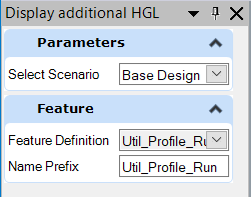
- Select the required
Scenario for HGL to be displayed, and the Feature Definition to use:
The same functionality is also available on the
context-sensitive toolbar when a drainage conduit is selected in a Profile
Model. This is provided for the case when the user has not created a Profile
Run, which might occur for a culvert.
Note: There is a preference on the backstage - File > Settings >
User > Preferences > View Options - Civil > Drainage and Utilities -
to Show Connected Conduits in Profile.
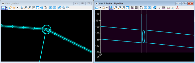
Above image shows the 2D Design Model in View 1 (on the left),
and a profile run in View 6 (on the right). In View 1, the conduits that are
included in the profile run are shown highlighted with direction arrows. The
conduit which is approximately vertical is not part of the profile run, but it
is connected to a node that is part of the profile run. In View 6, the profile
of the node shows the connected conduit as a circle (with a vertical
exaggeration).