Properties (Drainage and Utilities)
The following lists describe Utilities Conduit and Node properties:

- An internal index number for the conduit
- Label - the name of the feature
- Notes - any user-defined notes for the feature
- GIS-ID - if source of feature was in a GIS system, a GIS identification number unique to the database type may be shown here
- Node Reversal - allows user to reverse the direction of the conduit
- Start Node - the name of the node at the beginning of the conduit
- Stop Node - the name of the node at the end of the conduit
- Quality Level - the quality level of the feature as defined in ASCE Standard 38
- Authority - the quality level assigned and professionally sealed by an engineer, surveyor or other legally recognized professional
- Authority Description - a note field which may contain information about the registered professional such as name or registration number
- Investigation Level - a
field indicating the nature of the drainage investigation:
- Survey - indicates a rigorous survey was performed
- Engineering - indicates that methods more related to engineering were used. These methods might be as limited as a simple records search or perhaps as advanced as remote sensing using geophysical methods.
- Informational - indicates that a very simple records search or anecdotal evidence was used to determine the location
- Feature Definition - the SUE feature definition used
- Material - the material used for construction of the conduit
- Owner - the owner of the asset
- Operational Status - Abandoned, In-Service, Proposed, Removed, Temporary or Under Construction
- Network Type, Function, Conduit Type - see Drainage and Utilities Feature Definitions.
- Shape - the shape of the conduit
- Diameter or Rise/Span - the cross-sectional dimensions of the conduit
Drainage and Utilities Node Properties:

- An internal index number for the conduit
- Label - the name of the feature
- Notes - any user defined notes for the feature
- GIS-ID - if source of feature was in a GIS system a GIS identification number unique to the database type may be shown here
- Hyperlinks - allows storage of hyperlinks for information related to the node
- Quality Level - the quality level of the feature as defined in ASCE Standard 38
- Authority - the quality level assigned and professionally sealed by an engineer, surveyor or other legally recognized professional
- Authority Description - a note field which may contain information about the registered professional such as name or registration number
- Investigation Level - a
field indicating the nature of the drainage investigation:
- Survey - indicates a rigorous survey was performed
- Engineering - indicates that methods more related to engineering were used. These methods might be as limited as a simple records search or perhaps as advanced as remote sensing using geophysical methods.
- Informational - indicates that a very simple records search or anecdotal evidence was used to determine the location
- Rotation - the rotation of the node. All rotations are expressed as absolute values
- Elevation Top - the top elevation of the node. The location of this measurement is marked in the feature definition cells. See Drainage and Utilities Feature Definitions.
- Elevation Invert - the bottom elevation of the node. The location of this measurement is marked in the feature definition cells. See Drainage and Utilities Feature Definitions.
- Feature Definition - the SUE feature definition used.
- Material - the material used for construction of the node vault.
- Owner - the owner of the asset.
- Operational Status - Abandoned, In-Service, Proposed, Removed, Temporary or Under Construction.
- Network Type, Node Type - see Drainage and Utilities Feature Definitions.
- Length and Width - the plan
view (top down) dimensions of the vault. These measurements are used ONLY to
define a maximum envelope for the node. These numbers are populated by the
software but are not used in any real sense. They allow other 3rd
party software which do not understand the Bentley feature definition system to
build very simple models using the length and width combined with the top and
invert elevations.
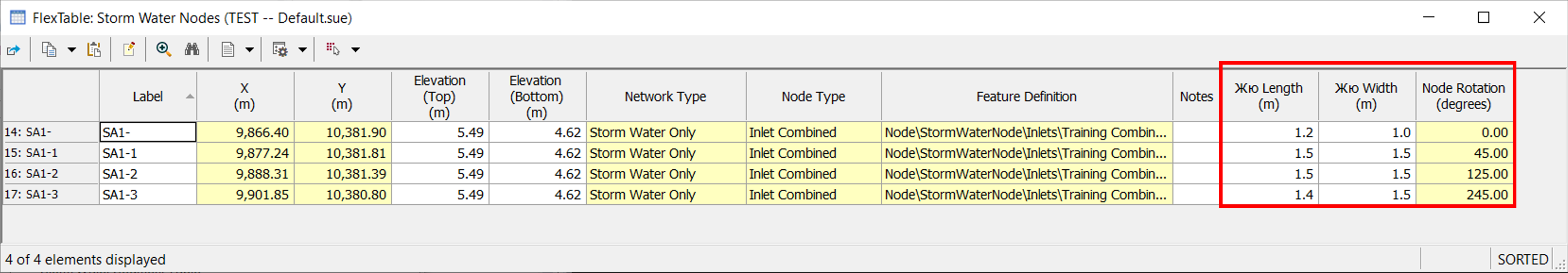
Note: In the Flex Table Storm Water Nodes the Length and Width values are different for different node rotations, this is because we don't know the size of the cells used to draw the node, and for nodes such as a street light, would you include the length of the arm? What we do know is the length and width of the bounding box that they fit in, which are the values that are shown and this is why different node rotations will cause different values.