Drainage and Utilities Feature Definitions
Introduction
Drainage and Utilities Feature Definitions are used to control symbology and define properties of utility elements. There are three types of Feature Definition for support of utilities workflows:
- Node Feature Definitions – A variation on civil Point type. It defines information for Utility Nodes, such as catch basins, manholes, valves and etc.
- Conduit Feature Definitions – A variation on the civil Linear type. It defines information for Utility conduits of all types, including drainage pipes, pressure lines, cables and ducts. Conduits are any linear utility feature including pipes, cables and ducts.
- Polygon Feature Definitions – Used to denote area features such as catchments (drainage areas).
Interface
Use of Feature Definitions in Commands
The feature definitions will be exposed in each command as shown in the example below. Thus each command will know how to construct and present the element being created.
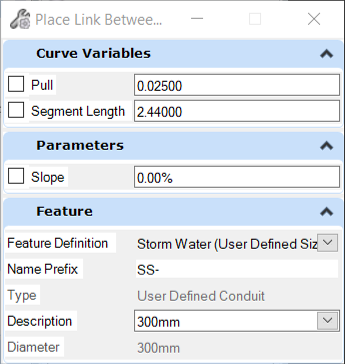
- The command will list feature definitions appropriate for the command. Node commands will present node feature definitions and conduit commands will list conduit feature definitions.
Interface for Creating and Editing Feature Definitions
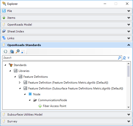
The Project Explorer > Design Standards tab is the interface for creating and editing feature definitions. Project Explorer is accessed from the File menu or from the Primary Tools toolbox. Feature Definitions are usually created and stored in DGN libraries.
Create New Feature Definitions
To create a new Feature Definition, right click at any branch of the feature definition tree to create new categories or any type of feature definition. Utility Feature Definition Types are Node, Conduit, and Drainage Area.
Properties Contained in Node Feature Definition

Feature Definition
- Name - Name of the feature definition
- Description - Optional description field
- Name Seed - Used for automatic naming of created features
- User Data Extensions - Used to select the User Data Extensions (UDX) that apply to this feature definition. For most types of UDX, the dialog lets you override the default value that was set in the UDX with one that is applicable to the selected feature definition. The exception to this is the Date/Time, and Real (Formula), types of UDX, the default value for which cannot be overridden. You can also choose whether the UDX is editable, or read-only.
- Default Height - Used to set the default height of a node. If you want the default height to match the height of the 3D cells, then this can be set to 0. If the node only uses one cell, such as for a headwall for example, then set this to 0. If you set this to a value that is greater than the combined height of the two 3D cells, then the gap between the two cells will be filled in automatically.
- Use Slope of Surface - Used to state whether the top 3D cell should slope at the same slope as the surface or element that was used to define its top elevation. Normally set to True for catch basins and manholes, and false for headwalls.
- Structure Type - Used to define the specific nature of the node. Varies by Utility type. For example for storm nodes, the types include grates, headwalls, and manholes. There is always a user defined option.
- Network Type - Used to define the specific type of network in which the node is used. For example, to distinguish between phone and CATV networks.
- Set Invert to Start / Set Invert to Stop – These fields apply to non-hydraulic conduits only - e.g. gas conduits, electric conduits, and not storm or sanitary conduits. These settings let the user control whether the inverts of the conduit match the inverts of the start and stop nodes to which they connect. If either is set to False, then that invert can be changed, in either the Civil or the Utility properties. If either is set to True, then that invert is read-only in the Civil and Utilities properties. Note that for hydraulic conduits (i.e. storm or sanitary) these fields are available in the prototype that the conduit feature definition uses. Non-hydraulic conduits do not use prototypes.
- Use Road Cross Slope - Used to state whether the Road Cross Slope value for a catch basin should be measured from the road surface. Set to False, then the value is read from the hydraulic prototype. Set to True, and a terrain model is selected as the Elevation reference, then the value is measured from it. The construction class, line style 3 alignment line in the plan cell determines the direction that the slope is measured.
- Road Cross Slope Offset - This is the offset, measured along the construction class, line style 3 alignment line in the plan cell, that is used as the start point to determine the Road Cross Slope. The slope is measured looking backwards, from this point towards the cell. If a negative slope is found - possibly because the offset value is too large and it positions the start point on the wrong side of a balanced roadway, then 0 will be returned as the Road Cross Slope. The default value for the Road Cross Slope should be larger than the width of the gutter tray - if present.
Hydraulic Prototype
- For manholes and catch basins, the Hydraulic Prototype defines a shape and size for the node, and these properties are used in some headloss calculations.
- For catch basins, the Hydraulic Prototype defines how its inlet capacity is calculated.
- For conduits, the Hydraulic Prototype defines whether it's a catalog or user-defined, the shape and range of sizes, or size.
- For catchment areas, the Hydraulic Prototype defines how runoff is calculated, and appropriate coefficients to do so.
These are just a few examples. It is therefore important to ensure that the Hydraulic Prototype for a drainage feature definition is correctly defined. Note though that these properties are only defaults - once the element has been placed these properties can be changed.

- Point - the Point Feature Symbology which controls the presentation of the node in plan views
- Profile - the Profile Feature Symbology which controls presentation in profile views.
- Connection Region - the Linear Feature Symbology which controls presentation of the connection region graphics.
- Solid - the Solid Feature Symbologies of the node in 3D.
The Feature Symbologies for point, profile, and connection regions each load an Element template. The Element Template contains the settings for that element - the level, colour, weight, cell etc., that are used when the graphic is placed in the DGN. The Feature Symbology for a solid is similar, but it will often load two Element Templates - one which describes the top portion of 3D model of the node, and one which describes the bottom portion (vault) of the node. Both will usually load 3D cells.
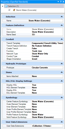
Properties Contained in Conduit Feature Definition
- User Data Extensions - Used to select the User Data Extensions (UDX) that apply to this feature definition. For most types of UDX, the dialog lets you override the default value that was set in the UDX with one that is applicable to the selected feature definition. The exception to this is the Date/Time, and Real (Formula), types of UDX, the default value for which cannot be overridden. You can also choose whether the UDX is editable, or read-only.
- Trench Template - allows assignment of a trench template from template library to be modeled with the conduit.
- Trench Feature Definition - Select a feature definition for the trench template. The feature definition contains four sections, which define a variety of settings and options:
- Create Trench - Controls whether a trench is created automatically when the conduit is placed. This setting is also available as a property of each individual conduit, so it can be controlled there as well.
- Function - varies by Utility type. For sanitary sewer segments, for example, the types include force main and gravity. There is always a user-defined option.
- Network Type - varies by subtype and describes the nature of the network.
- Single Gradient - This field applies to non-hydraulic conduits only - e.g. gas conduits, electric conduits, and not storm or sanitary conduits. Defines whether or not the conduit has a single, constant gradient between the start and stop nodes. If this field is set to False, then when you place a conduit you are prompted for a surface, as well as the start and stop nodes, and the conduit will follow the surface at the depth of cover that is defined for it in the Conduit Table.
- Conduit Type - varies by utility type. Provides ability to define the nature of the conduit, whether pipe or duct, pressure or gravity, etc.
- Shape - the cross-section shape of the conduit. A variety of standard shapes are supported including Irregular (IE user defined). Only available for non-hydraulic conduits, and hydraulic conduits if the SUDA_USE_HAESTAD_CONDUIT variable is set to 0.
- Shape Orientation - Defines
the origin of the cross-section shape.
- Soffit - The shape is oriented along the feature such that the inside top follows defined profile elevations.
- Center - The shape is oriented along the feature such that the center of pipe follows defined profile elevations.
- Invert - The shape is oriented along the feature such that the inside bottom follows defined profile elevations.
- Conduit Table - Defines a
list of available sizes for the conduit. This table is used as follows:
- For non-hydraulic conduits - e.g. gas, electric - not storm or sanitary.
- For hydraulic conduits - i.e. storm or sanitary - it is only used when the SUDA_USE_HAESTAD_CONDUIT configuration variable is defined and set to 0. Normally, it is expected that this variable will be defined and set to 1, which it is by default. In this case the linked prototype is read, which usually has a conduit catalog as one of its properties, and this is used to define the available sizes. If the prototype is set up to use a User Defined Conduit, instead of a Conduit Catalog, then its size is used.
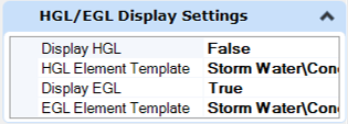
HGL/EGL Display Settings
- Center Feature Symbology - Controls the presentation of the conduit center in plan views.
- Outer Element Template - Controls the presentation of the conduit outer walls in plan views.
- Inner Element Template - Controls the presentation of the conduit inner walls in plan views.
- Outer Profile Element Template - Controls the presentation of the conduit outer walls in profile views.
- Inner Profile Element Template - Controls the presentation of the conduit inner walls in profile views.
- Profile Feature Symbology - Controls the presentation of the conduit in profile views.
- Solid Feature Symbology - Controls the presentation of the conduit in 3D.
The Feature Symbologies for linear, profile, and solid each load an Element template. The Element Template contains the settings for that element - the level, colour, weight, etc., that are used when the graphic is placed in the DGN.

Plan, Profile and 3D Templates – These work the same as in the road/site tools.
- Plan - the element template which controls the presentation of the conduit in plan views.
- Profile – the element template which controls presentation in profile views.
- 3D – controls presentation of the conduit in 3D.
Note the use of Symbologies in some cases, and Element Templates in others. Symbologies are used when there is a need to specify an Annotation Group, such as for the center of a conduit. Element Templates are used to control symbology where there is no need for annotation, such as for the walls of a conduit.
For larger conduits, which might be used for culverts for example, you might not want to display the conduit centre in plan. However, you will probably want to annotate it. In this case, edit the Center Feature Symbology, and set its Element Template to None.
A similar workflow covers the case where you want to display the conduit walls in profile, but not the centre. Edit the Profile Feature Symbology, and set its Element Template to None.
For smaller conduits, which might be used for cables for example, you might not want to display the conduit walls in profile - just the center. In this case, set the Element Templates for the Inner and Outer Profile Element Templates to None, and set the Element Template in the Profile Feature Symbology.
If you have a conduit that has a large range of sizes, and you want to see display the conduit centre in plan for smaller sizes but not for larger sizes, then this can be achieved using two feature definitions - one for each range of sizes.
Comparison of Road and Site versus Utility Feature Definitions
- Utility Feature Definitions are not integrated with the Feature Definition Toggle Bar.
- You cannot change feature
definitions between types, for example to change a water line feature to a gas
line feature definition. If you need to do this, the recommended workflow is:
- Use ModelBuilder to export the relevant features to external files. Shapefiles are recommended for conduits, because they store the geometry along the conduit, including any bends
- Delete the features from the DGN
- Use ModelBuilder to import the external files - setting the feature definitions appropriately so that the correct utility types are created .