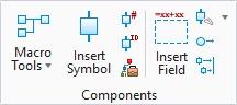
Insert Symbol By Device ID
 Used to place objects in the
current model by the symbol Device ID.
Used to place objects in the
current model by the symbol Device ID.
Accessed from:
| Setting | Description |
|---|---|
| Filter Devices | Allows you to filter the list of displayed device IDs. By selecting the appropriate radio button you can restrict the filter to Terminal/Plugs or Devices (non-terminals/plugs). Select or enter any combination of Installation, Location, Tag, Part Number and Function Text and then select the Search button. Any device IDs that match all the entries will be listed. If the Ignore Case check-box is selected, the case of entered letters will not be taken into account. |
| Display Tab |
|
| Show Devices Tab |
|
| Symbol List |
The software lists all the symbols that match any filters that you have applied. You can apply additional filters by selecting a field heading and picking the down arrow which displays all the values for that field. Picking a value will filter the list of symbols and only list those that have that value. Clicking on a field heading will sort the list in ascending order. Clicking a second time will sort it in descending order. You can click and drag the fields in any order you wish. Right clicking on any field heading will allow you select which fields from the database you wish to display. You can toggle on/off fields as desired. You can select the symbol that you want to place from the list. |
| Preview Tab | Shows a preview of the symbol for the selected device based on the current drawing mode. |
| Settings Flyout |
Selecting the down arrow on this button will flyout the button menu with 3 choices:
|
| Place Symbol | Places a new device, based on the symbol settings specified. |
Row indicators are as follows:
- X = If the device has no family and the symbol is placed in the current drawing mode. Or if the device has a family, a symbol has been placed for every role (parent, child, cable, terminal, pin, etc.) in the family. Whether the family is compound, standard, terminal, or cable, a symbol is placed in every role. (This should be the existing rule for when we show X.)
- / = Applies only to schematic mode for devices that have a family assigned. If a symbol has been placed for at least one non-parent role in the family but not every non-parent role, then this should be displayed. Again, pay no attention to the parent role when determining whether to show a /. (This is the modified rule for when to show /.)
- Blank = Any other row in the grid. Based on these rules, if a symbol has been placed only in a parent role but not in any of the child roles of a family, then the device should still have a blank value in the left-most column.