Place a Route using Single Line mode
-
Select a routing component tool; e.g. a rectangular duct
 ( Place
Ducts).
( Place
Ducts).
The ribbon bar shows a contextual tab. A small segment of duct (icon) appears on the pointer, and the Place Component tool settings dialog appears.
-
Set the Placement options required in drawing a route.
Ensure the required duct type catalog is activated in Place Component dialog.
-
Check the
 (Single-Line Mode)
option on the
tab to begin with route in a single
line.
(Single-Line Mode)
option on the
tab to begin with route in a single
line.
The Placement (Justification) options automatically void for single line mode.
-
Click in the view to select data point to locate the route start
point.
The free end of the new duct is dynamically attached to the pointer.
-
Select the end point/next point for the new duct.
The duct route appears in a single line presentation. The nodes appear at turns and connections signify their type (viewed with mouse hover).
-
To draw a diverted duct segment, change the route's direction by
selecting another point that is not inline with the previously selected points.
The tool automatically places a Bend at the node joining the last segments placed.
Note: The Bend typically is the default fitting, and when promoted would result as an elbow set in Auto Fitting option. You can however, override the node catalog to suit your design.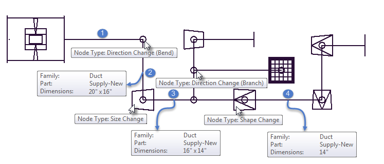
Segment 2 -> 3: Rectangular Duct size changes from 20x16 to 16x14; Segment 3 -> 4: Duct shape changes from Rectangular to Round;
- (Optional)
Connect the duct terminal to an opening / exhaust fitting such as
a diffuser placed at an elevation by setting the base offset and type (rigid or
flex) in case of round duct.
The diffuser gets hooked up in the route at vertical drop value of given offset.
-
Reset to complete the route.
The route will also have endcap symbols added at the open terminals.
-
To add a source of air handling, place an equipment, such as fan
or AHU connecting it at the beginning of the route.
The single line route is ready for analysis or manipulating.