AECOsim Building Designer Help

Properties For: Exposed roof dialog box

Contains controls used to view and define properties for exposed roof surface types. Exposed roof surfaces are ceilings or roof sections inside rooms or spaces above ceilings that are exposed to the outside of the building, directly in contact with the outside air. The exposed roof contains properties that all surface sub-types share as well as properties specific to the exposed roof sub-type.


Opens when the Exposed roof Project Tree object´s pop-up menu is activated in the AECOsim Energy Simulator Project Tree dialog box and the Properties menu item is selected.

Exposed roof Construction detailsThe properties panels under the Construction details heading contain controls used to view the selected exposed roof construction details. The properties displayed here are saved in the AECOsim Energy Simulator materials database’s constructions definitions. Constructions can be viewed, manipulated and created using controls and settings found on the Materials Manager dialog box.


Note: The Properties For: Exposed roof dialog box is a specialized instance of the Properties dialog box which displays common surface properties and special exposed roof properties.

Tip: Units Display – Units are displayed using the default system of units that was defined for the project, but can be changed to display using alternative units.

SettingDescription
Category

Displays the surface category. Category is a read only property.

Sub type

Used to view or change the surface Sub type from Exposed roof to another roof or ceiling sub-type. The Sub type drop-down list is filtered and contains only floor and ceiling sub types.

Name

Used to enter a name for the exposed roof. The name entered here appears appended to the exposed roof object on the AECOsim Energy Simulator Project Tree dialog box.

Construction

Used to view of change the exposed roof material construction definition.

Dimensions

Displays overall dimensions of the selected exposed roof.

  • Length — Disabled for the exposed roof sub-type.

  • Width — Disabled for the exposed roof sub-type.

  • Height — Disabled for the exposed roof sub-type.

  • Area — Displays the total area of the selected exposed roof.

  • Volume — Disabled for the exposed roof sub-type.

  • Orientation — Displays the orientation of the exposed roof relative to the building orientation. Building orientation is defined in the Properties For: Building dialog box.

View factor to ground Automatically calculated by default (Calculate view factor to ground is checked). The auto-calculated value assumes horizontal ground. If the ground slopes significantly upward or downward as you move away from the building, the auto-calculated view factor to ground could be incorrect.
Calculate view factor to ground When on, View factor to ground is automatically calculated. Use this option when the ground is horizontal.

When off, the value for View factor to ground is entered manually. Use this option when the ground slopes significantly.
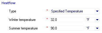
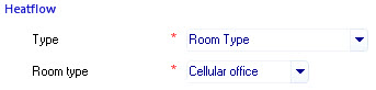
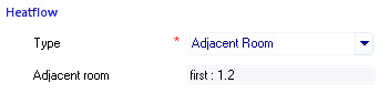
Heatflow

Contains controls used to view and set Heatflow data for the exposed roof. Heatflow refers to the energy transfer occurring through a surface’s material construction. Heatflow is established automatically as rooms are created. AECOsim Energy Simulator determines if the adjacent space above the room ceiling is in contact with another room. If no adjacent room is found above the ceiling, the surface is defined as being of the surface sub-type exposed roof.

  • Type — Used to display and modify the nature of the heatflow occurring through the exposed roof.

    • None – When selected, the surface is considered to have no energy transferred through it. For instance, when the surface is a virtual wall. This is almost never selected for an exposed roof sub-type.

    • Specified Temperature – When selected, heatflow through the exposed roof will be calculated based on the values entered for winter and summer temperatures in the two available temperature options.


      – The temperature options are only visible when the heatflow type is set to Specified Temperature.

      • Winter temperature – Specifies the winter temperature outside the exposed roof.

      • Summer temperature – Specifies the winter temperature outside the exposed roof.

    • Room Type – When selected, heatflow through the exposed roof is calculated based on the standard room type of its parent room.


      • Room type – Lists the room types available for the project.

    • Adjacent Room – When selected, the heatflow through the surface is calculated by the conditions in the Adjacent Room.


      • Adjacent room – This option is not selectable due to the exposed roof being of the surface sub-type exposed roof. Heatflow can not be calculated using this option.

    • Ground – When selected, the heatflow through the exposed roof is transferred from contact with the ground. Energy from the ground depends on factors such as the ground temperature which depend upon the project site’s location, the weather profile, and the local topography and soil type.

    • External – Ground is the default heatflow type for exposed roofs. When selected, the heatflow through the exposed roof is transferred from the conditions outside the building. Energy from the environment outside the building depends factors such as the weather profile and external shading.

Common

Displays common construction details for all surface sub-types. Common construction details are read only properties.
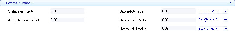


  • Category — Displays the construction category associated with the surface.

  • Total thickness — Displays the surface total thickness which included all the material layers (solids and air gaps) that make up the construction.

  • Decrement factor (internal) — Displays a Decrement factor associated with the construction’s inside surface. The Decrement factor is used to calculated the amount a thermal wave is decreased in intensity during its propagation process from the outside to the inside of the surface construction.

  • Decrement factor (external) — Displays a Decrement factor associated with the construction’s exterior surface. The Decrement factor is used to calculated the amount a thermal wave is decreased in intensity during its propagation process from the outside to the inside of the surface construction.

  • Fixed thermal properties — Used to display the surface construction setting related to its thermal properties which are defined in the Materials Manager dialog box. When on, calculated surface emissivity and absorption coefficients are overridden, enabling you to define your own thermal properties (in the Materials Manager dialog box). When off, the calculated transmission values are used.

  • Admittance (internal) — Displays the amount of heat that passes through a unit area of the constructions’s inside surface, when its external face is subject to a unit temperature change.

  • Admittance (external) — Displays the amount of heat that passes through a unit area of the constructions’s external surface, when its inside face is subject to a unit temperature change.

  • Time lag (internal) — Displays the time it takes for heat generated by the sun to transfer from the outside, through the construction, to the inside surface of the construction into the building envelope, and affect the internal conditions.

  • Time lag (external) — Displays the time it takes for heat lost to transfer from the inside, through the construction, to the external surface of the construction from the building envelope.

  • Weight (internal) — Displays the construction inside surface’s weight per unit area.

  • Weight (external) — Displays the construction external surface’s weight per unit area.

External surface

Contains controls used to display thermal transfer properties for external surface types such as the exposed roof. External surface construction details are read only properties. External surface construction details are defined using the controls on Materials Manager .


  • Surface emissivity — Displays the construction surface emissivity factor. Surface emissivity is a measure of the efficiency in which a surface emits thermal energy. It is defined as the fraction of energy being emitted relative to that emitted by a thermally black surface (a black body). A black body is a material that is a perfect emitter of heat energy and has an emissivity value of 1. A material with an emissivity value of 0 would be considered a perfect thermal mirror.

  • Absorption coefficient — Displays the absorption coefficient for the construction's external surface. The absorption coefficient is a number between 0 and 1. The lower a construction's external surface solar absorption coefficient, the less solar heat it transmits.

  • Upward-U-Value — Displays the calculated outside surface U-value or thermal transmittance of energy traveling upward through the selected construction.

  • Downward-U-Value — Displays the calculated outside surface U-value or thermal transmittance of energy traveling downward through the selected construction.

  • Horizontal-U-Value — Displays the calculated outside surface U-value or thermal transmittance of energy traveling horizontally through the selected construction.

Layers

Contains controls used to display the surface’s construction material layers in a read only table. The table displays thermal properties for each layer such as the thickness, density, conductivity, specific heat and vapor resistivity.


Simulation Reports
  • Inside face temperature - When on, the temperature of the inside face of the surface (i.e., the side of the surface construction that faces toward the inside of the room) is included in the simulation output results (Simulation - Results Viewer).
  • Outside face temperature - When on, the temperature of the outside face of the surface (i.e., the side of the surface construction that faces away from the room) is included in the simulation output results (Simulation Results Viewer).
  • Incident solar radiation - When on, the total solar radiation incident on the outside face of the surface (i.e., the side of the surface construction that faces outdoors) is included in the simulation output results (Simulation Results Viewer).
  • Transmitted solar radiation - When on, the total (beam plus diffuse) solar radiation entering the room through a window is included in the simulation output results (Simulation Results Viewer).
Note: The two face temperature output variables can be selected for any surface that is included in the project (exposed walls, exposed roofs, ground floor, partitions, windows, etc.).
Note: The two solar radiation output variables can be selected for "exposed" surfaces (exposed to outdoors). Incident solar radiation can be selected for any surface that is exposed to outdoors (e.g., exposed wall, exposed roof). Transmitted solar radiation only applies to windows that are located in surfaces that are exposed to outdoors. These options are disabled for interior partitions or interior windows.
Notifications panel

Used to validate project data and resolve issues with project data in real time (as it is being entered in the Properties For: dialogs) via errors, warnings and messages.