Place Node
 Used to create a node.
Ribbon
Layout > Layout > Place Node
Workflow
Select Reference Element for Node Elevation. Reset to Type an Elevation - pick the element that you want to use to define the top elevation of the node. This can be a linear element which has an active profile, a mesh, or a terrain model. The elevation normally represents the top of the cover for a chamber. Press Reset if you want to enter an elevation.
Define Location - define a point to locate the node (by clicking in the graphics, Civil AccuDraw, or snapped to other graphics). Note that the text of the prompt tells you the type of node being place, such as Place Manhole for example. If you chose a reference element in the previous prompt, then this prompt lets you define a vertical offset from that element. If you pressed Reset, then this prompt lets you type in an elevation.
Select Rotation Mode - choose whether you want to define the rotation of the node using an absolute value, or relative to an alignment (which can be any linear element).
If you choose Absolute, then next prompt is to Select Rotation or Reset to Place again. The rotation is defined as an absolute value, using the settings defined in File > Settings > File > Design File Settings > Angle Readout. If Civil AccuDraw is used the define the location of the node, then the compass will lock to the nearest compass point, which is defined in the Civil AccuDraw Settings. The rotation value is still absolute - it will not update if the element selected in Civil AccuDraw Station and Offset is subsequently modified.
If you choose Relative to alignment, then the next prompt is to Locate Reference Element for Rotation. Select a linear element, from the active design file or a reference. The next prompt is to Select Rotation or Reset to Place again. The rotation value is relative to the selected linear element, and will be updated if the element is subsequently modified.
Feature Definition - Defines the feature definition to be assigned to the new node.
Name Prefix - the feature definition provides a default naming prefix, which can be overridden here.
Notes:
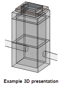
After the rotation is entered the node is created and modeled. The node will be presented in plan model and 3D model as defined in the feature definition.

- The command reverts back to prompt 2 to allow additional nodes to be placed.
- You can change the feature definition at any time, for example so that the second node uses a different feature definition to the first.
- If you click reset, the prompt sequence reverts back to prompt 1 to let you pick a different reference element.
The value defined for the rotation of a node is applied to the construction class, line style 3 lines in the cells that make up the 2D and 3D definition of the node.
When a node is placed relative to a surface, the top of the node will rotate to match the slope of the surface. Compare the two catch basins below. The one on the left is set to orient the top to the surface. The one on right is not. In Workspace Preferences there is a setting to define the threshold for automatically setting the orientation property to true. If the slope of the surface is less than this threshold then orient is set to True. You can change the Orient to Surface property at any time.

The orientation can be toggled on and off in the properties of the node.
Manipulators
- Move Node manipulator can be used to move the node.
- Node Top Elevation manipulator can be used to enter an elevation for the top of the node, if the node was placed using a typed in elevation. This manipulator is greyed out if the node was placed using a reference element.
- The Rotation manipulator can be used to change the rotation of the node.
Properties
Select the node and click Properties to access the graphical and spatial properties of the node. Select the node and click Utility Properties to access the hydraulic properties of storm and sanitary nodes, or Subsurface Utilities properties for any type of node.