Construction of Cells Used in Feature Definitions
Subsurface Utility Design & Analysis uses MicroStation cells for two purposes.
The cells are utilized as follows:
- The user defined cells are defined in an element template. The element template is then utilized in a feature definition, which defines presentation of the nodes in the plan, profile and 3D models.
- A 2D cell will define the desired plan space representation. If a cell is not defined for plan space then a generic shape is used.
- The 3D model will be defined by two 3D cells which define the top structure and vault of the node.
- Points of interest in the nodes (such as hydraulic center, insertion point and allowable connection points) will be defined by way of attributed elements in the cells.
The Plan Space Cell
In plan space the needs are as follows:
- Represent the basic shape of the node for purposes of laying out the nodes in relationship to surfaces and horizontal geometry.
- Serve as the graphical entity which is plotted on sheets, plans and reports of various sorts.
A MicroStation cell is used for this purpose. An example is shown below:
These are ordinary MicroStation 2D cells. The complexity of the graphic is dependent on user needs and preference. The examples above is a simple representation of a plan view catch basin which is a common usage, since they serve to provide a plan space indication of the position, shape and size of the grate only. These cells are normally drawn according to the real world size of the node.
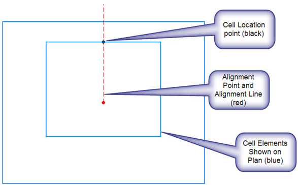
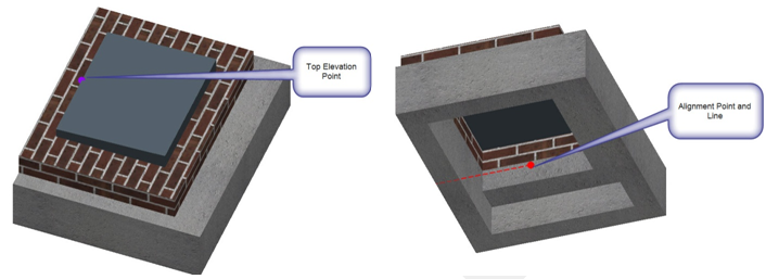
Note the special designations in the plan cell. These are definitions made in the plan cell and created using construction class elements and a specific linestyle as follows:
- Cell Location point – construction class point element of linestyle 4 – defines the location of the node. For example, a node placed at a certain station and offset is measured to this point.
- Alignment Point and Alignment line – construction class elements of linestyle 3. The alignment points are defined in 2D and 3D cells and are used to align the different cells relative to each other in X,Y plane. The alignment line allows orientation of the multiple cells rotationally.
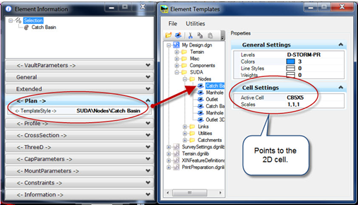
The plan cell is defined in the element template which is called by the feature definition for plan symbology.
Cells for 3D Model
The feature definition contains definitions for cells which are used to model the node in 3D. The necessary cells are as follows:
- A 3D MicroStation cell drawn in as much detail as a user desires which is an adequate model of the top of the node. "Top" is defined as the portion of the node above the pipe which always exists regardless of the height of the structure, in other words the minimum part that is always built. This may include grates, lids, slabs and other appurtenances. A more accurate model will also include a short segment of the vault so that the top cell will dimensionally match the vault cell.
- A 3D MicroStation cell drawn in as much detail as user desires which is an adequate model of the vault (bottom) of the node. This cell will also include any sumps which are part of the vault. The height of the vault cell will be modeled such as to create a node of minimum depth when joined with the top cell and tall enough to allow for the largest acceptable size of conduit expected to connect to the vault.
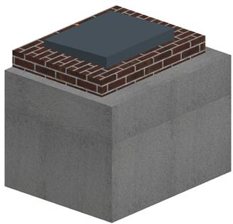
Example of a 3D structure with top and bottom cells combined:
Key Points and Regions Defined in the 3D Cells
Similar to the location and alignment points defined above in 2D cells, there are some needed definitions in the 3D cells as well.
A bottom cell defines the shapes and special points in the vault of a node structure:
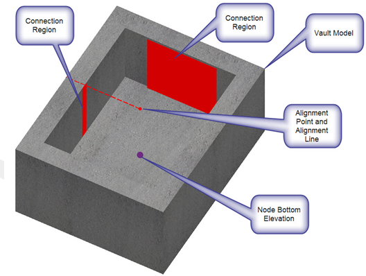
- Alignment Point and Alignment line – construction class elements of linestyle 3. The alignment points are defined in 2D and 3D cells and are used to align the different cells relative to each other in X,Y plane. The alignment line allows orientation of the multiple cells rotationally.
- Connection Regions – these
define locations on the face of the vault where conduits can connect. These are
defined as construction class elements with line style 6.
- For rectangular vaults a shape on the face of the bottom cell is used – If it is desired that pipes can connect only at specified points, then make a very narrow shape. Multiple regions can be defined per side if multiple pipes are allowed to connect.
- For circular vaults a cone surface element on the face of the bottom cell is used – pipes can connect perpendicularly anywhere around the vault.
- Node Bottom Elevation Point – Construction class element with line style 5. The point at which elevations are determined. In bottom cell defines where the flow line elevation is measured. If a sump is required in the node, then this point would be set above the bottom of the node model.
A top cell defines the 3D model of the top of the node structure:
- Alignment Point and Alignment line – Construction class elements of linestyle 3. The alignment points are defined in 2D and 3D cells and are used to align the different cells relative to each other in X,Y plane. The alignment line allows orientation of the multiple cells rotationally.
- Node Top Elevation Point – Construction class element with line style 5. The point at which elevations are determined and also defines the hydraulic center. In top cell defines where the rim elevation is measured.
The notes above describe the use of two 3D cells, which is normal for chambers. Each of the two cells includes a construction class, line style 5 point, which is used to define the elevation (either the rim or the flow line). An exception to this is for headwalls, as these are modelled using one 3D cell. In this case, the cell can include two construction class, line style 5 points. If it does, then the Default Height property in the feature definition for the headwall must be set to zero. This technique could be used for other types of node, such as a street light or traffic sign for example, where the height is fixed, and you want to be able to connect a conduit to it, at a specific depth.
How the 3D Model is Constructed
When a node is placed the 3D model is generated by:
- The 2D cell is placed in the plan model, using the location point to define its position. Rotation is about the location point.
- The bottom cell is placed in 3D using the Bottom Node Location Point at the flow line elevation. The alignment point and alignment line is matched to the alignment point/line in the 2D cell.
- The top 3D cell is placed in
the 3D model:
- The Node Elevation Point in the top cell uses the elevation derived for the node from the surface or reference feature.
- The alignment point and alignment line is matched to the alignment point/line in the 2D cell.
- The elevation point is aligned vertically with the Node Location point from the 2D cell.
- The bottom 3D cell is placed in the 3D model:
Summary
- Feature definitions for all node types will link to a series of Feature Symbologies.
- Feature Symbologies will link to a series of MicroStation Element Templates for symbology and presentation.
- The plan space template will include a 2D cell of user's design. This cell is placed in plan space for all plans production activities.
- The 3D presentation normally
points to two templates.
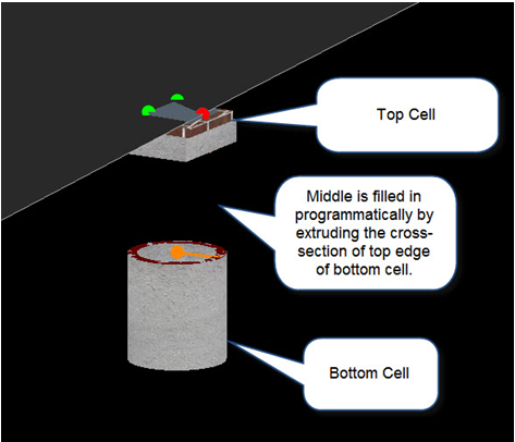
- The first defines a 3D cell that models the physical nature of the top of the node.
- The second defines a 3D cell that models the physical nature of the bottom of the node.
- The two cells are joined by extruding a slice of the bottom cell upwards to meet the top cell.
- If the top cell is blank, then no extrusion is done and only the bottom cell is placed.
- The plan, top and bottom cells will contain various attributed elements to define key points and regions necessary for: