Place Conduit
Place Conduit creates a conduit between two independent nodes.
The characteristics of the Place Conduit command are:
- Utilize a feature definition which defines conduit characteristics
- Will create the conduit to connection points defined in the nodes
- Will model the conduit in 3D
Interface
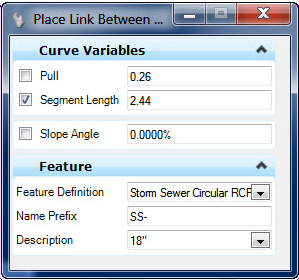
- Pull and Segment Length – used to define a curved conduit layout by applying a deflection at each joint. Disabled except when entering curved conduit mode and radius is zero.
- Radius – radius of a curved conduit layout. Disabled except when entering curved conduit mode and pull/segment length are zero
- Slope – user defined slope along the conduit
- Feature Definition – Defines the feature definition to be assigned to the new node. User can choose feature definition by:
- Description – A conduit feature definition can contain multiple definitions for size. The available, defined dimensional variations are available here.
Elevations
Elevations at the conduit ends are determined as follows:
- Conduit Feature definition will contain a minimum depth of cover property. Minimum depth of cover will result in an elevation at the end points.
- If you enter a slope on second prompt the slope may result in an elevation on the second node which is different than the minimum depth of cover for the conduit or the node cell.
- The nodes will have an invert elevation point defined in the bottom 3D cell. This is the elevation that will be used in absence of other information.
Properties
When selected, the properties of a conduit will be shown and editable in the MicroStation property panel (Element Info and Quick Properties).
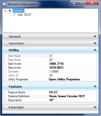
- Names of the start and stop nodes. These are where the conduit connects.
- Invert Elevations of the conduit at each end.
- Diameter or Rise/Span – the dimensions which define the conduit.
- Feature name and feature definition.
- Description – Conduit size in a drop down list. The user may change size by choosing any entry in the table. Table consists of all entries defined in the conduit table for the feature definition.
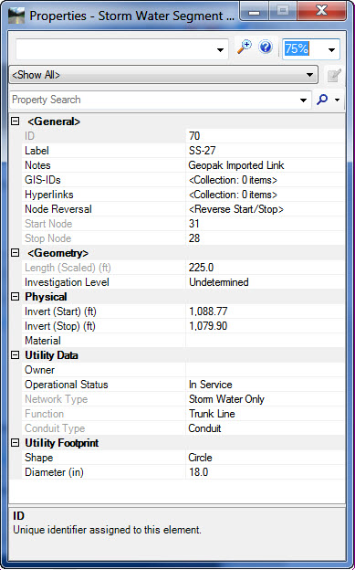
Open Utility Properties provides a shortcut to a second properties dialog, which provides more details.
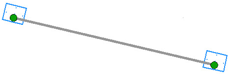
Remove the picture that's immediately below this text. If you like, you could add a link to the Utilities View > Element Views > Utility Properties, as a source of further information.
Manipulators
When the conduit is selected the manipulators as shown below will be presented. These are presented only in 2d space. 3D manipulators may prove useful in future releases but are not included in this release.
The presented manipulators will function as follows:
- Move End Point Drag Handle – click on this handle allows moving the conduit end point. Once clicked then the end point moves and user can click on another connection point on the same node or a different node.
- Slope – a text manipulator for slope of the conduit.
- Elevations – text manipulators for elevations at each end.