Release Notes - Subsurface Utilities CONNECT Edition
Compatibility with Haestad Products
This version of Subsurface Utilities is based on the Haestad CONNECT Edition release (10.00.00.40), so data created in Subsurface Utilities has binary compatibility with the current StormCAD, CivilStorm, SewerCAD and SewerGEMS products. It is not backwards compatible with previous versions of Subsurface Utilities.
Importing Data
Importing InRoads Storm and Sanitary data requires the 64-bit version of the Microsoft database access engine to be installed. Previous versions of the Civil products have used the 32-bit version of this engine, because they were 32-bit.
This link will let you download the engine. You will be asked which version (32 or 64-bit) you want once you have started the download process. Note that you will need to uninstall the 32-bit version of the engine before the 64-bit version will install.
User Interface
Subsurface Utilities now uses the 'ribbon' style of interface. The ribbon now gives access to all relevant functionality that is available in the Haestad Storm-Sewer products (subject to licensing).
Licensing
Subsurface Utility Engineering (product ID 2335) is now included in the licence for OpenRoads Designer CONNECT Edition - it is not a separate licence.
StormCAD for 100 inlets is included in the licence for OpenRoads Designer CONNECT Edition. Usage of product ID 2174 is no longer logged.
Feature Definitions
Feature Definitions for a node now include the ability to set the default height of a node. Previously a node would be extruded if its height was less than a default value. If you want the height of a placed node to be the same as the combined height of its two 3D cells, then set this value to 0.
Feature Definitions for a node now include the ability to state whether the top of a node should use the slope of the surface or not. Previously, this setting was only available in Element Info, after the node had been placed.
Feature Definitions for a non-hydraulic node (i.e. not a storm or sanitary node) now include the ability to state whether all the elevations of the conduits that connect to that node should be the same or not. Previously, if you had more than one non-hydraulic conduit (say a communications duct for example) connected to a node, then changing the elevations of one conduit caused the elevations of the other conduits that also connected to the same node to be updated. This behaviour may not be desirable when non-hydraulic conduits are being designed, where they may have different depths of cover depending on whether they are under a road or not.
Feature Definitions for a non-hydraulic conduit now include the ability to state whether the elevations should be calculated using a depth below a chosen terrain model or mesh. Previously, if the Place Conduit tool was used, then the elevations would have been obtained from the start and stop nodes, and the conduit would have followed a single gradient. This behaviour may not be desirable when non-hydraulic conduits are being designed, and they need to be at a set elevation below a surface.
Feature Definitions for a conduit now include the ability to state whether the elevations refer to the crown, or base, of the conduit. Previously, you could choose between soffit, centre, and invert. This functionality is most likely to be used when utilities are extracted from 3D graphics.
Feature Definitions now use the point, linear, surface, and solid feature symbologies, in preparation for Drawing Production. Note that only a subset of the element templates that can be defined in feature symbologies are used by Subsurface Utilities.
User Data eXtensions (UDX)
UDX are used to store your own business data. Previously, UDX were defined at an element type level, so - for example - they applied to all Comms Nodes. Now, you can choose the UDX for a feature definition, making them much more granular. A Comms node could be a cabinet, a pole, or a chamber, and each might need to have different data stored against it, and this can now be achieved. Note that you need to add two CFG variables to read SUE UDX from a DGNLib - SUE_SEED_FILE and SUE_SEED_MODEL. These two variables operate in the same way as the existing SUDA_SEED_FILE and SUDA_SEED_MODEL variables.
Configuration Variables
A new configuration variable - CIVIL_SUBSURFACE_FILTERS_DGNLIBLIST - has been added. This points to the dgnlib file from which utility filters are loaded. Previously, the CIVIL_CIVILTMDGNLIBLIST configuration variable was used to load both utility filters and terrain model filters.
Conduit Shapes
Subsurface Utilities now supports the same conduit shapes as the Haestad Storm-Sewer products. Previously there was no support for some open channel shapes and irregular conduit shapes.
3D Model
All conduit shapes are now automatically modelled in 3D. Previously it was necessary to use templates to model some 3D shapes, such as for open channels for example.
General Improvements
A profile element is now automatically created when a conduit is placed, so a trench template can be attached to it if required. Previously you had to manually open the profile model of each conduit to create the profile element.
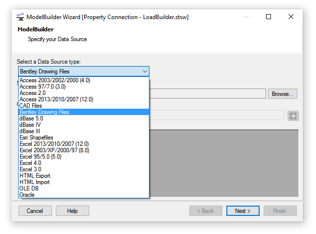
If ModelBuilder is used to create or update a Hydraulic Analysis model, you can now choose a feature definition to use for each imported table. This functionality was previously only available when creating or updating a Subsurface Utility Engineering model.
If a conduit is raised, such that the invert elevation of a connected node becomes lower than it needs to be, then the invert elevation of the node is now adjusted. Previously it was not, and required a manual alteration.
The properties of a utility conduit that has been created using Extract from Graphics, and draped on a terrain model, now include the vertical offset used, and this value can be adjusted if needed.
A property has been added to a conduit to state whether it has a Single Gradient or not. Hydraulic conduits will normally be at a single gradient, but utilities which have been extracted from 2D graphics and draped on a terrain will not be.
A property has been added to a node so that you can choose a reference linear feature, such as a road centerline. If one is selected, the station and offset are calculated by raising a normal from the node to the linear feature, and these values are automatically updated if the node or the linear feature is moved. The values are displayed in Utility Properties and FlexTables.
Undo / redo functionality has been improved. Previously, two or more clicks were often needed to undo an action.
Save As DWG has been enhanced so that the DWG now includes the names of the Subsurface Utilities elements, such as nodes and conduits. This means that you can now open a DWG created from the 3D model in Autodesk Navisworks, and then use DataTools to import Subsurface Utilities data from Excel, to attribute the model. Previously this workflow was not possible because although Subsurface Utilities writes the element names to Excel, they weren't in the DWG, which meant that a mapping between the two was not possible.
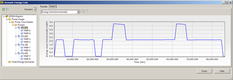
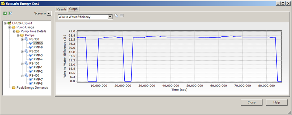
Pump Energy Costs
This release introduces a new Energy Cost tool which optimizes pump operations. With this tool you can now analyze the cost of operating pumps (by the energy used) during a single extended period simulation scenario.
The scenario energy cost analysis determines the energy cost by pump for all pumps selected by the user. Pricing for energy cost is set up in the Pricing button in the energy costing manager. Price functions are assigned to individual pumps in energy costing.
Results can be viewed in tabular format or graphed.
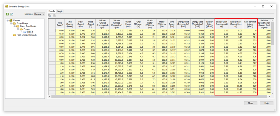
Depending on the selection, results can show data for a single pump or pump station.
SWMM Enhancements
Updated EPA SWMM Version
This release uses EPA SWMM version 5.1.010.
See the wiki for more information: EPA SWMM solver versions used by SewerGEMS and CivilStorm
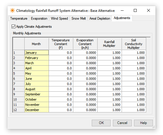
New SWMM Climatology Monthly Adjustments Table
The SWMM extension Climatology now includes the "Adjustments" tab. Checking the Apply Climate Adjustments box enables the Monthly Adjustments table, where you can define Temperature Constant, Evaporation Constant, Rainfall Multiplier, and Soil Conductivity Multiplier adjustments by month.
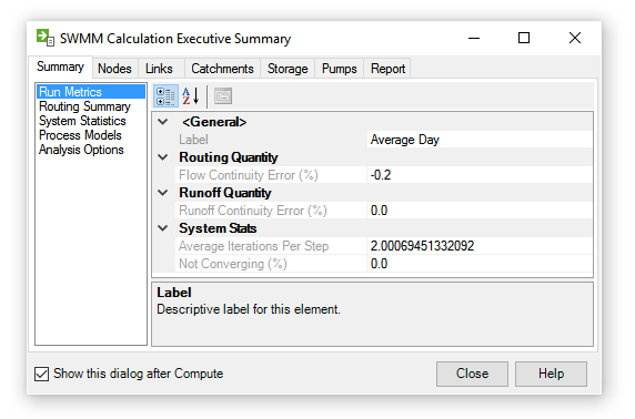
New SWMM Calculation Executive Summary
In previous versions, after successfully computing a model with the SWMM solver a large text file would be created and opened with an external text editor, such as Notepad.
Starting with this release, an internal dialog provides the SWMM Calculation Executive Summary. This makes it much easier to browse or find results.
This dialog displays values using the hydraulic model's units. In prior versions, the results were displayed in US Customary units regardless of the hydraulic model's defined units.
New SWMM Calculation Options
The Explicit (SWMM) default Routing Time Step was reduced from 30 seconds to 5 seconds for better stability. The default value for Use Variable Time Step is now True.
- The Minimum Variable Time Step is the smallest time step allowed when variable time steps are used. The default is 0.5 seconds. Smaller steps may be warranted, but they can lead to longer simulation runs without much improvement in solution quality.
- The Number of Threads is the number of parallel computing threads to use on machines equipped with multi-core processors. The default is 1.
The SWMM Default Infiltration Method has the new option "Green and Ampt (Modified)". This modified version of the original Green and Ampt method no longer redistributes upper zone moisture deficit during low rainfall events. The original authors of SWMM's Green-Ampt model have endorsed this modified version. It will produce more infiltration for storm events that begin with low rainfall intensities, such as the SCS design storm distributions.
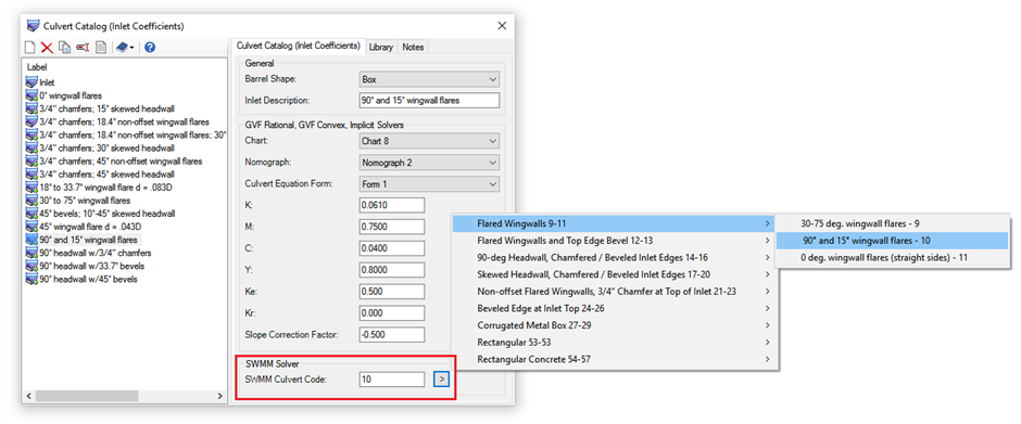
SWMM Culvert Support
Culverts can now be modeled by the Explicit (SWMM) solver.
When exporting a model to SWMM the culverts in the engineering libraries will now be converted with their associated SWMM culvert codes. This allows the culvert to be recognized when the model is opened in SWMM.
The Section "SWMM Solver" has been added to the Culvert Catalog dialog. You can either enter the "SWMM culvert code" or you can click the ">" button to select the culvert from a menu.
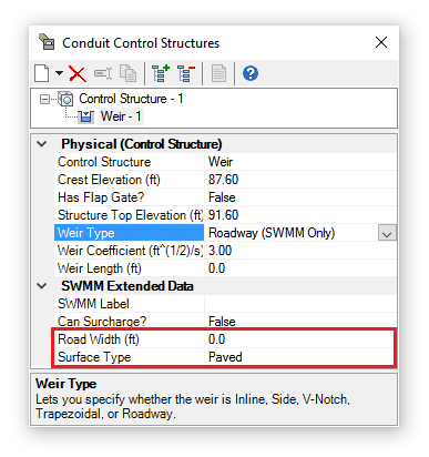
New Roadway Weir
A new type of weir, a ROADWAY weir, has been added. It models roadway overtopping using the FHWA HDS-5 method and would typically be used in parallel with a culvert conduit to route bypass to the downstream node. This is available for the Explicit (SWMM) solver; with the Implicit solver, you can use the roadway overtopping weir option in the conduit properties when setting the conduit as a culvert.
The fields Road Width and Surface Type are specific to the Roadway weir type.
Low Impact Development (LID) Enhancements
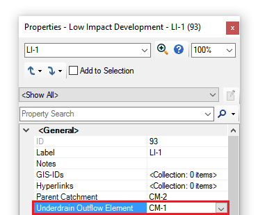
New LID Underdrain Target Option
The LID element has the new field "Underdrain Outflow Element" which lets you specify an element that will accept underdrain flow from the LID.
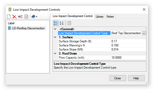
New LID Control Type
LID control type now includes the option Roof Top Disconnection.
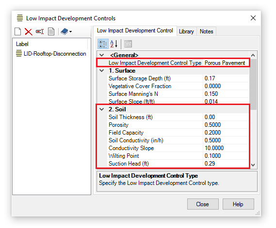
New Soil Fields for Porous Pavement Type LID Control
A Soil section has been added to the LID control type Porous Pavement as shown below. This allows you to model a sand filter or bedding layer beneath the pavement.
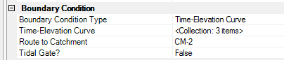
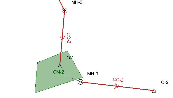
Outfall to a Catchment
The field "Route to Catchment" is now available for the outfall element when using the Explicit (SWMM) solver. This field allows you to specify the catchment to which flow will be routed from the outlet.
Improved Performance
Other general improvements have been implemented to reduce the computation time when using the SWMM Solver.
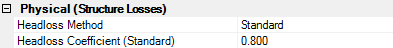
Structure Headloss Calculations
Starting with this release, the Explicit (SWMM) solver supports structure headloss calculations. Structures can now use the headloss methods "HEC-22 Energy (Third Edition)" and "Standard".
Tractive Stress
When conduits and channels have sufficient tractive stress they are essentially self-cleaning in that particles will either not settle or they will be re-suspended if they do.
Starting in this release, tractive stress is included in constraint-based design.
See:
Help "Tractive Force Design"
Wiki Tractive Stress (aka Tractive Force, Shear Stress) Calculations and Design
Graphs
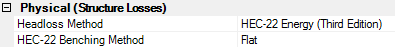
More meaningful steady state graph
If the current scenario is steady-state (available with the GVF Convex/SewerCAD solver), the default graph is a bar chart for the selected elements. Elements from different scenarios can also be added in the Series Options dialog. The Series Options dialog can be used to customize the information displayed in the graph (scenarios, elements, and fields).
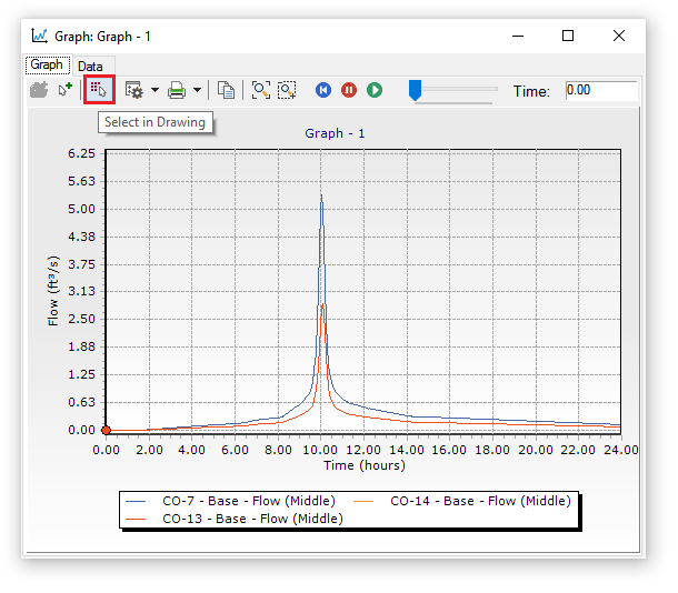
"Select in drawing" in graphs and graph manager
In the graphs manager you now have an additional option "Select in Drawing" which is to the right of "Add to Graph". When a saved graph is selected and you click this button it will select the elements that are part of the saved graph. Any existing selection will first be cleared. Only elements that are checked in the graph options will be selected in the drawing.
Profiles
Engineering Profile Annotation Table
Engineering profiles now have the option to include an annotation table which is drawn similar to the analysis profile.
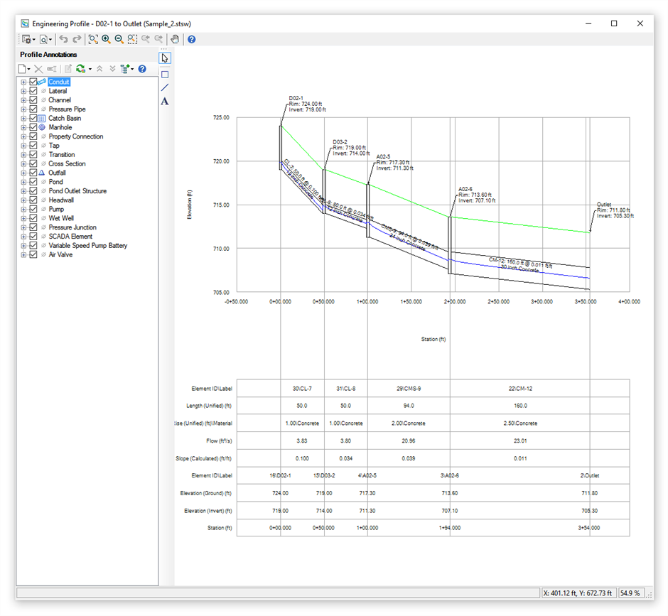
However, the displayed fields and field order can be edited in the engineering profile which makes it more customizable.
To toggle the annotation table display, click on the down arrow next to the Chart Settings icon and select "Show Profile Annotation Table" from the dropdown menu.
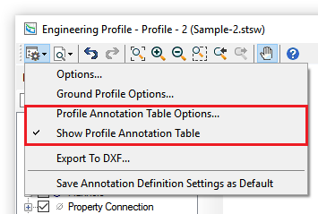
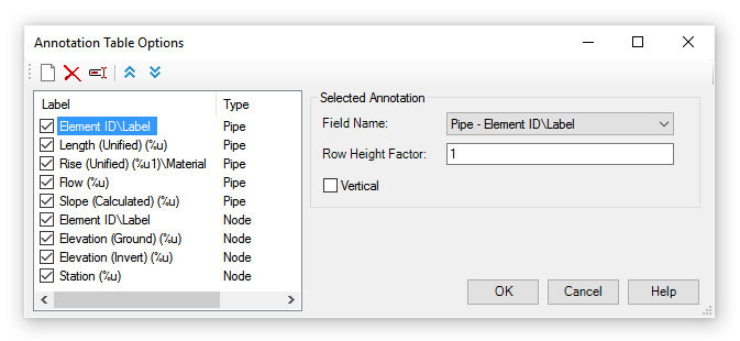
The annotation table options can be edited by selecting "Profile Annotation Table Options…" from this dropdown menu.
Customizable Reports
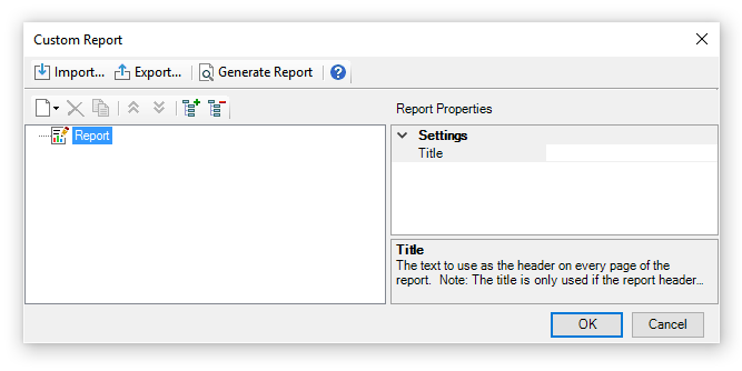
A new Custom Report tool has been added to the Report tab. This tool allows you to quickly assemble a customized report which can contain user input, results, graphs, etc. You can now define the template interactively instead of modifying an XML file manually (which can still be done).
The Report Options dialog allows you to control how reports are displayed (e.g. font, header, footer, margins).
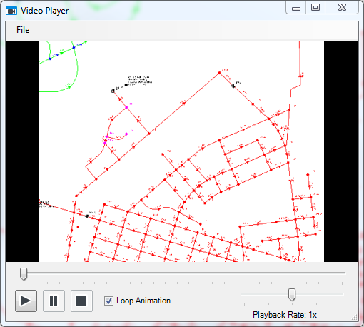
Record AVI video from time results
The AVI Screen capture enhancement allows you to record videos of scenario animations. You can select which portion of the screen will be recorded. The screen capture utility will capture and record all the frames of the animation within the bounds you specify and produce an AVI video file which is shareable outside of the storm and sewer products.
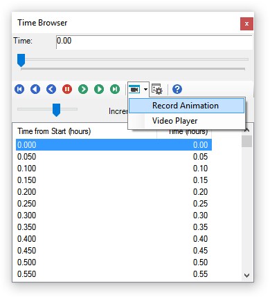
An internal video player allows you to watch the video after it is done recording.
Open on Selection From Within FlexTable
When you have a FlexTable open, you can now select the rows in the table based on the current selection.
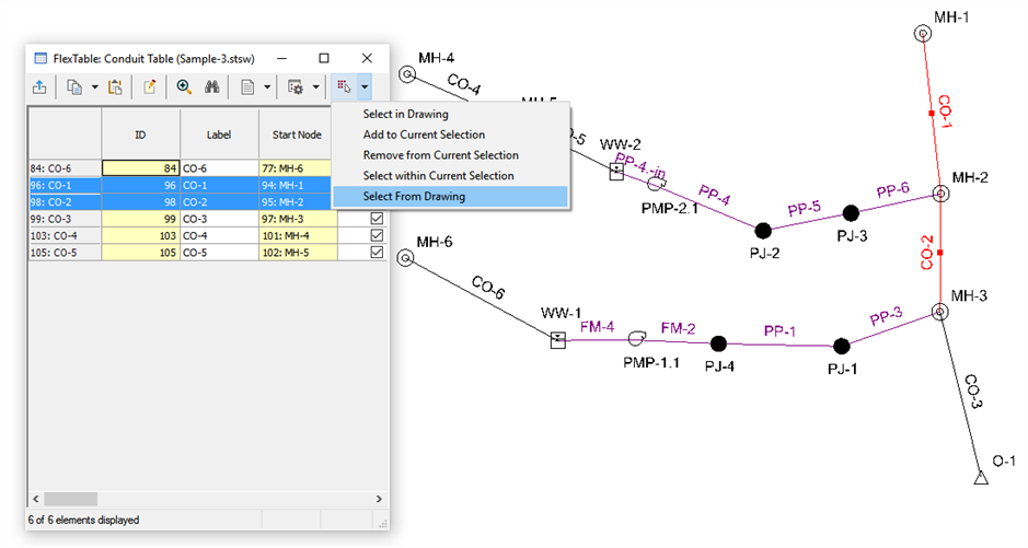
- Select some elements.
- Open a FlexTable for one of the selected elements and click the drop-down for the "Select in Drawing" button.
- Click the last item, "Select from Drawing".
- If there are any elements for the type of table you currently have open, it will select the rows for the elements selected.
- You can then filter down the contents of the table by right-clicking the row header and clicking on "Open on Selection".
Double-click on Dropdown List to Toggle Through Values
When editing data in the property grid you can double-click the label to change the value. This applies to Boolean fields (those that show true/false values); reference fields (i.e. zone); and enumerated fields (i.e. Status (Initial)). When you double-click any of these field types it will cycle through the available values in the drop-down list. Commands like "Edit" for reference fields are excluded during the cycling.
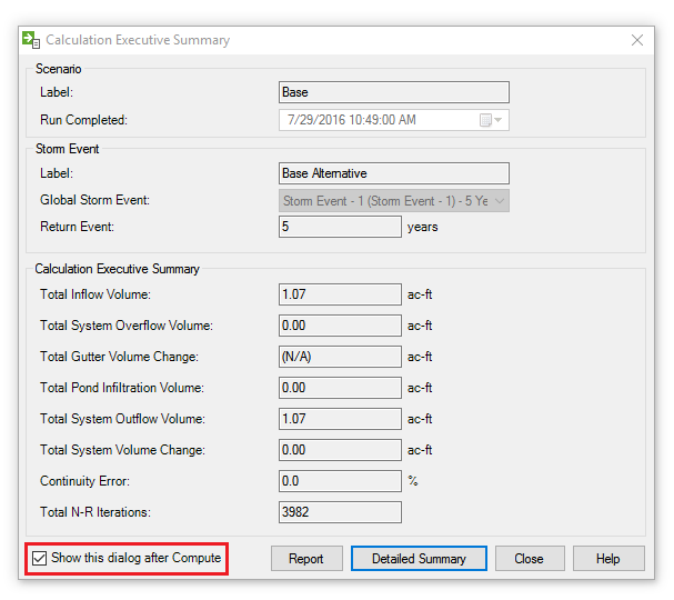
Option to Auto-close the Calculation Summary Dialog After Computing a Model
The Calculation Executive Summary dialog box opens after you compute a model. You now have the option to not automatically open the dialog after a compute by unchecking "Show this dialog after Compute". This option applies to all available solvers for the product. This is a global option and once unchecked applies to all projects opened in the product.
The post-calculation summary dialog now allows you to choose if it displays after computing a model as seen in the image below.
Excel Export Option Available in All Platforms
FlexTables can be exported to an Excel file in multiple products (SewerGEMS, SewerCAD, StormCAD, and CivilStorm) and for all integrated platforms (MicroStation, AutoCAD, ArcMap, and stand alone).
InRoads IDF Importer
InRoads IDF files can now be imported into an engineering library storm event group which can then be used by SewerGEMS, StormCAD, CivilStorm, or PondPack. This can be done as a batch process with an external tool or individually using the Storm Data dialog.
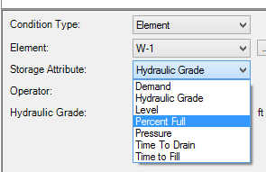
Ability to Use Wetwell %full as a Condition with SewerCAD Controls
Wet well control conditions now include the storage attribute "Percent Full".
Note: Controls only apply to the "GVF-Convex (SewerCAD)" numerical solver. If using the "Explicit (SWMM)" or "Implicit (SewerGEMS Dynamic Wave)" numerical solvers, pump controls must be defined in the properties of the pump. Controls do not apply to the "GVF-Rational (StormCAD)" numerical solver.
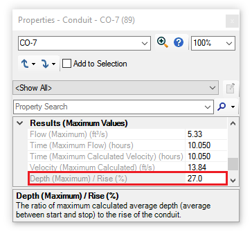
Maximum Depth/Rise Property Added to Conduits to Identify Flooding/Surcharging
Conduits now have the property "Depth (Maximum) / Rise (%)" which displays the ratio of maximum calculated average depth (average between start and stop) to the rise of the conduit.