Used to apply structural
attributes to a slab, free, or linear form.
Used to apply structural
attributes to a slab, free, or linear form.
Accessed from:
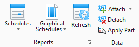
- Ribbon:
StationDesigner >
By default, these forms are not structural. The Apply
Structural Attributes to Slab/Free/Linear Form tool performs two functions, and
can perform these two functions at once. You can apply structural data to a
slab or free form without applying analytical data. This by itself creates a
structural solid. For linear forms, applying structural data creates a
structural wall.
Structural solids can be exported as CIS/2 and SDNF data.
This does not apply to structural walls.
If you apply both structural and analytical data, you will
create structural solids or walls, and you will add a plate. A plate is an
analytical representation that you add to the structural solid or wall. When
you add structural and analytical data to slab, free, or linear forms, they
become visible in an analytical view window, and the analytical data will be
exported to an analysis package.
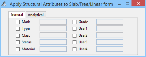
When you use this tool, you do not have to complete any of
the fields on the General tab. Just selecting the slab, free, or linear form is
enough for it to be recognized as having structural data. If you do not have
 (Analytical
Features) turned on, when you use this tool, the Analytical tab will not
be visible and you will not be applying analytical data at the same time. If
you want to apply analytical data to a structural solid or wall later, you can
use this tool again with Analytical Features turned on.
(Analytical
Features) turned on, when you use this tool, the Analytical tab will not
be visible and you will not be applying analytical data at the same time. If
you want to apply analytical data to a structural solid or wall later, you can
use this tool again with Analytical Features turned on.
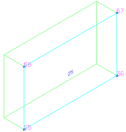
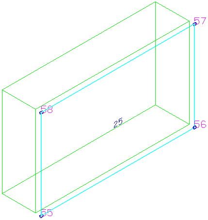
If a structural solid or wall has a hole (subtractive
feature), its corresponding plate (the analytical representation) will have the
same hole cut in it. See the procedure below.
| Setting | Description |
|---|
| General tab
|
Used to apply specific structural data. You do not
have to complete any of the fields to add the status of having structural
attributes to the slab.
-
Mark - Sets the identification mark for
the structural component, e.g.
1B-1.
-
Type - Sets the type of structural
component, e.g.
Floor or
Wall.
-
Class - Sets the class for the
structural component, e.g.
Primary.
-
Status - Sets the status for the
structural component, e.g.
New.
-
Material - Sets the type of material for
the structural component, e.g.
Concrete.
-
Grade - Sets the grade for the
structural component, e.g.
4000 psi.
-
User1 - 4 - Sets user defined variables
1 through 4 for the structural component.
|
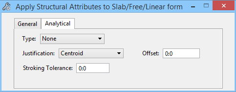
| Analytical tab
|
Used to apply specific analytical data.
-
Type - Enter the type of analytical
element. Values are:
-
None - The structural solid or wall
will not have a type associated with it.
-
Floor - The structural solid or wall
will have a type of
"floor" associated with it. This data is
used for structural analysis.
-
Wall - The structural solid or wall
will have a type of
"wall" associated with it. This data is
used for structural analysis.
-
Justification - Enter the type of
justification. As with linear placement points (top-center, bottom-left, and so
forth), this will determine how the analytical element (the plate) is placed in
relation to the structural element (the structural solid or wall). Values are:
-
Centroid - The plate is placed as a
centroid to the structural solid or wall.
-
BackFace - The plate is placed at
the back face of the structural solid or wall.
-
FrontFace - The plate is placed at
the front face of the structural solid or wall.
-
Offset - Enter the distance in master
units to offset the plate from the structural solid or wall.
-
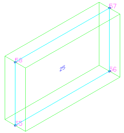
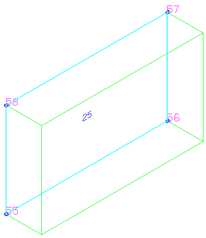
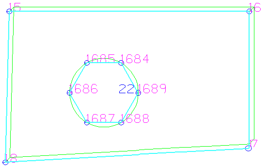
Stroking Tolerance - If the base shape
of a structural solid is an ellipse or a complex shape, or otherwise contains
curved segments and therefore cannot be represented as a simple polygon, its
plate in an analytical view will be in summed segments because not all
analytical software packages can interpret curves. The stroking tolerance
represents the maximum distance between a line segment and the actual curved
member itself.
Tip: A low number means that you want
the analytical element drawn as closely as possible to the same shape as the
physical element.
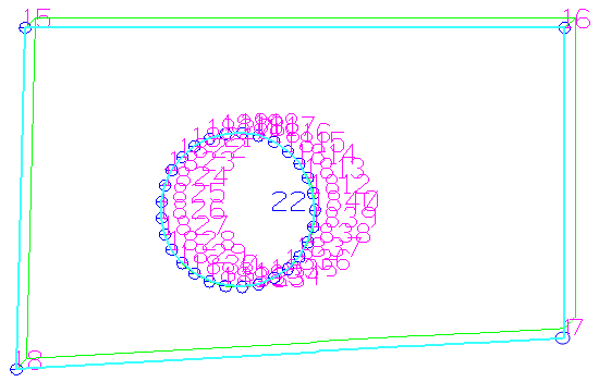
Small
Stroking Tolerance example
|
Key-in:
STFMODIFY
CHNGFORM